Getting Started with the MC56F81000-EVK
Contents of this document
-
Plug It In
-
Get Software
-
Build, Run
-
Create
-
Learn
Sign in to save your progress. Don't have an account? Create one.
Purchase your MC56F81000-EVK
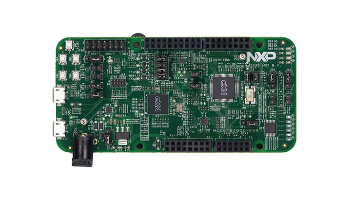
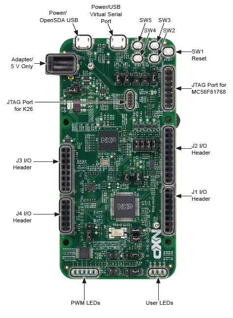
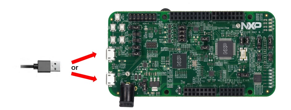
1. Plug It In
Let’s take your MC56F81000-EVK for a test drive!
2. Get Software
Installing software for the MC56F81000-EVK
2.1 Install your toolchain
NXP offers a complimentary toolchain called CodeWarrior IDE. There are many versions of this IDE, to support MC56F81xxx, the latest CodeWarrior for MCUs 11.1 is needed.
Get CodeWarriorIn order to support MC56F81xxx, it's necessary to update the CodeWarrior IDE.
Install CodeWarrior 11.1
- Launch CodeWarrior 11.1, then go to Help -> check for
updates.
-
-
In the list of available update sites, select NXP MCU Eclipse
– Update Site.
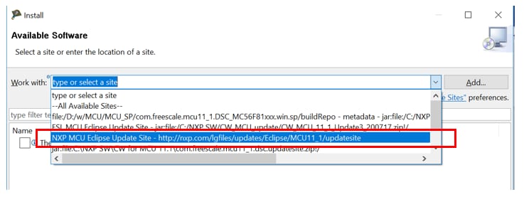
-
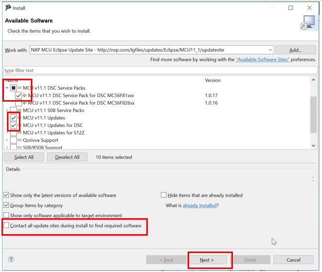
Notice the updates listed in the Install menu, check the boxes for ‘ MCU v11.1 DSC Service Pack for DSC MC56F81xxx ', ‘ MCU v11.1 Updates ' and ‘ MCU v11.1 Updates for DSC '. Uncheck the box next to ‘ Contact all update sites during install to find required software '. Then click Next.
-
Follow the prompts until it completes the installation and prompts for restart of CodeWarrior Development Studio. Click Yes and the tool will restart and the installation of the updates is complete.
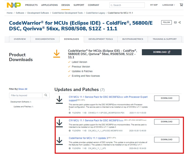
2. Offline install CodeWarrior v11.1 Update3 + Service Pack for DSC MC56F81xxx
-
Download the install files for CodeWarrior v11.1 Updates3 and service pack for DSC MC56F81xxx from CodeWarrior SSP.
-
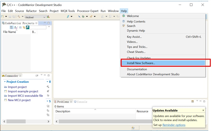
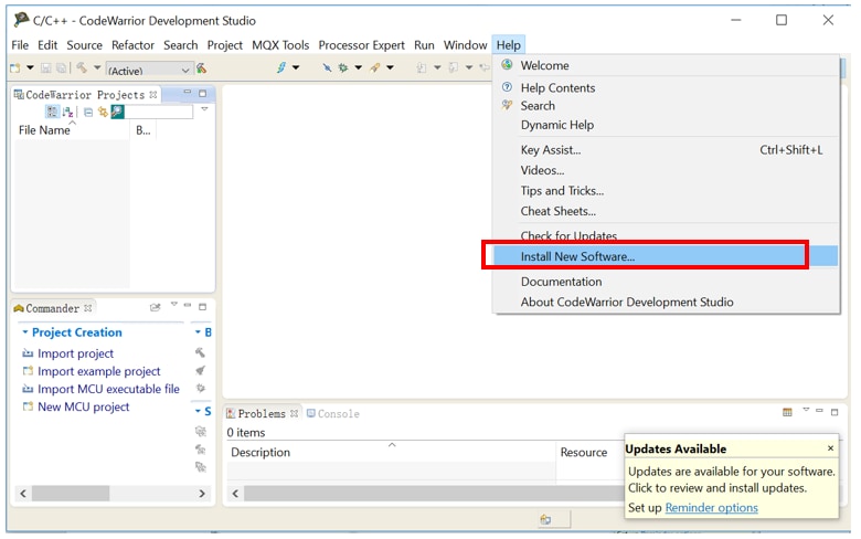
Launch CodeWarrior v11.1, then go to Help -> Install New Software
-
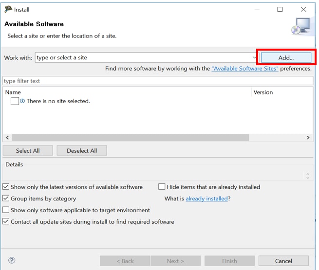
From the Install menu, select Add
-
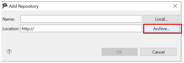
Select Archive
-
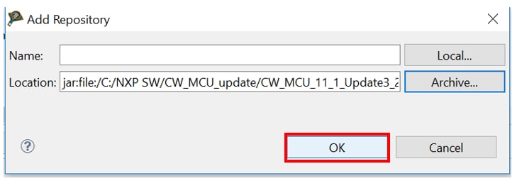
Navigate to the update file downloaded
CW_MCU_11_1_Update3_200717.zip, select and click open.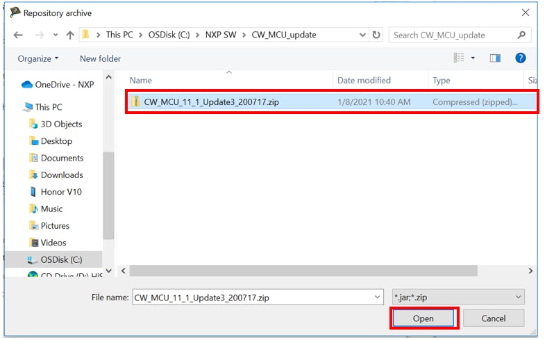
-
Click OK.
-
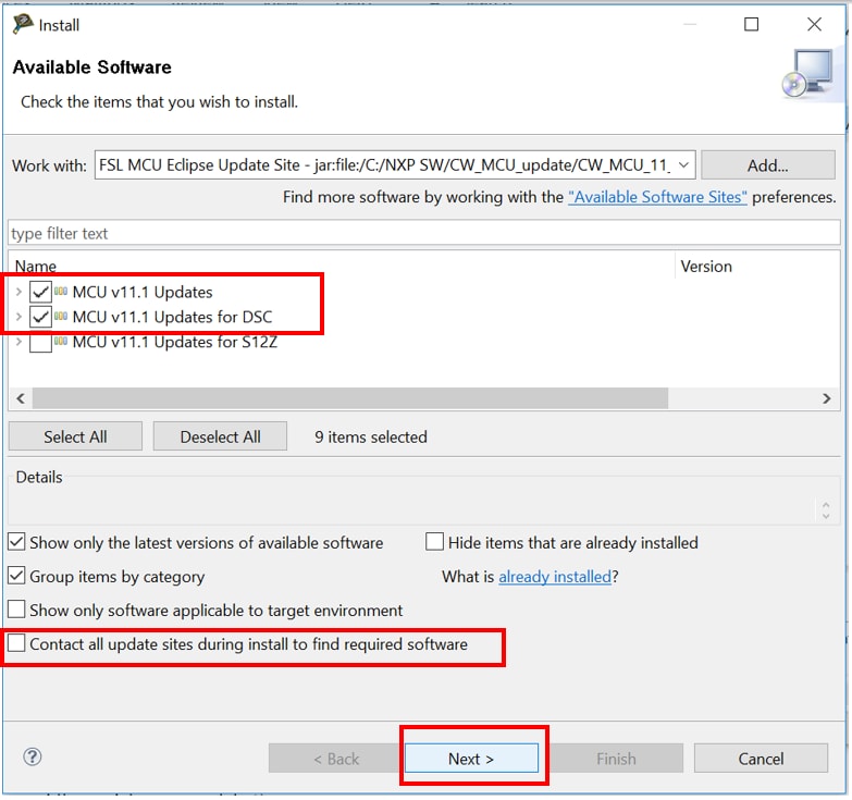
Notice the Updates listed in the Install menu, check the boxes for ‘ MCU v11.1 Updates ' and ‘ MCU v11.1 Updates for DSC '. These updates are cumulative, so all previous updates are included. Uncheck the box next to ' Contact all update sites during install to find required software '. Then click Next.
-
Follow the prompts until it completes the installation and prompts for restart of CodeWarrior Development Studio. Click Yes and the tool will restart and the installation of the updates is complete.
-
Repeat step 5~8 for downloaded service pack for MC56F81xxx (com.freescale.mcu11_1.DSC_MC56F81xxx.win.sp.v1.0.17.zip).
Install CodeWarrior 11.1
- Launch CodeWarrior 11.1, then go to Help -> check for
updates.
-
-
In the list of available update sites, select NXP MCU Eclipse
– Update Site.
-
Notice the updates listed in the Install menu, check the boxes for ‘ MCU v11.1 DSC Service Pack for DSC MC56F81xxx ', ‘ MCU v11.1 Updates ' and ‘ MCU v11.1 Updates for DSC '. Uncheck the box next to ‘ Contact all update sites during install to find required software '. Then click Next.
-
Follow the prompts until it completes the installation and prompts for restart of CodeWarrior Development Studio. Click Yes and the tool will restart and the installation of the updates is complete.
2. Offline install CodeWarrior v11.1 Update3 + Service Pack for DSC MC56F81xxx
-
Download the install files for CodeWarrior v11.1 Updates3 and service pack for DSC MC56F81xxx from CodeWarrior SSP.
-
Launch CodeWarrior v11.1, then go to Help -> Install New Software
-
From the Install menu, select Add
-
Select Archive
-
Navigate to the update file downloaded
CW_MCU_11_1_Update3_200717.zip, select and click open.
-
Click OK.
-
Notice the Updates listed in the Install menu, check the boxes for ‘ MCU v11.1 Updates ' and ‘ MCU v11.1 Updates for DSC '. These updates are cumulative, so all previous updates are included. Uncheck the box next to ' Contact all update sites during install to find required software '. Then click Next.
-
Follow the prompts until it completes the installation and prompts for restart of CodeWarrior Development Studio. Click Yes and the tool will restart and the installation of the updates is complete.
-
Repeat step 5~8 for downloaded service pack for MC56F81xxx (com.freescale.mcu11_1.DSC_MC56F81xxx.win.sp.v1.0.17.zip).
2.2 Jump-Start Your Design with the MCUXpresso SDK
The MCUXpresso Software Development Kit (SDK) is complimentary and includes full source code under a permissive open-source license for all hardware abstraction and peripheral driver software.
Click below to download the latest SDK release for the MC56F81000-EVK.
Get MCUXpresso SDKYou can also use the online SDK Builder to create a custom SDK package for the MC56F81000-EVK.
2.3 FreeMASTER
FreeMASTER is a user-friendly real-time debug monitor and data visualization tool that enables runtime configuration and tuning of embedded software applications. Click below to download the latest FreeMASTER.
Get FreeMASTERIn order to use the CP210x USB to UART bridge virtual COM port communication on MC56F81000-EVK, download and install the CP210x drivers.
CP210x drivers2.4 MCUXpresso Config Tools
The MCUXpresso Config Tool is an integrated suite of configuration tools that guides users in creating new MCUXpresso SDK projects, and also provides pin and clock tools to generate initialization C code for custom board support. MCUXpresso Config Tools v8.1 or higher version is needed.
MCUXpresso Config Tools2.5 Serial terminal
Many of the MCUXpresso SDK examples output data over the MCU UART. Make sure you install an terminal application.
Not sure how to use a terminal application? Try one of these tutorials: Tera Term Tutorial, PuTTY Tutorial
3. Build, Run
3.1 Explore the Bare-mental Example Code
According to MC56F81000-EVK hardware, lots of bare-mental demo application and driver examples that not base on SDK and Config tool are developed. Click below to download the ‘MC56F81000-EVK Demo Examples’
MC56F81000-EVK Demo Examples3.2 Explore the MCUXpresso SDK Example Code
The MCUXpresso SDK comes with a long list of example applications code. To see what's available,
browse to the SDK boards folder of your SDK installation and select evkmc56f81000
SDK_Install_Directory>/boards/evkmc56f81000
To learn more about specific example code, open the readme.txt file in an example’s directory.
3.3 Build, Run
If one or more of the demo application or driver examples sounds interesting, you’re probably wanting to know how you can build and debug yourself. The following guide provides easy, step-by-step instructions on how to open, build and debug an example code using the CodeWarrior IDE.
Install CodeWarrior 11.1
- Launch CodeWarrior 11.1, then go to file -> Import.
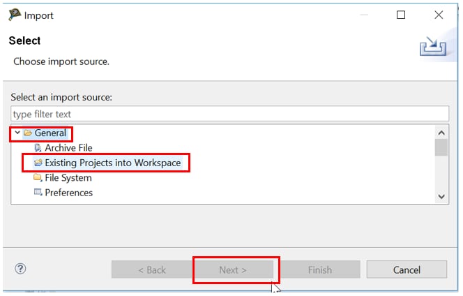
- In the list of import source, expand the General tree control and select Existing projects into Workspace. Then click Next
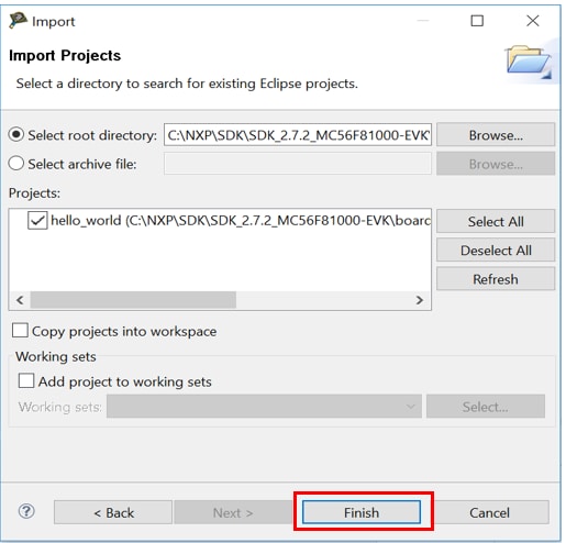
- Select Browse
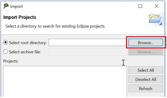
- Navigate to the example projects downloaded,
SDK_Directory/boards/ evkmc56f81000/demo_apps/hello_world, select codewarrior and click OK.
- The selected project appears in the Projects list, click Finish
Note:Don’t modify the project here, otherwise the SDK package will be changed. Don’t send this project to others, because it’s a linked project to your SDK package. See next section about how to create a new standalone project.
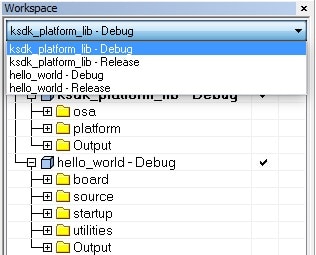
Build an Example Application
Now the project appears in the CodeWarrior Project view of the Workbench window. The project have two build configurations with different optimization configuration. ‘flash_ldm_lpm_debug’ is configured as Speed optimization level 1, ‘flash_ldm_lpm_release’ is configured as Speed optimization level 4
- Click the tool bar Debug icon, and select Debug Configuration
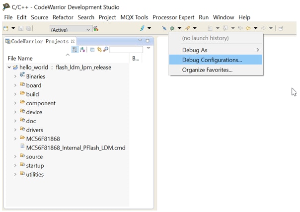
- The Debug configurations dialog box appears. expand the CodeWarrior tree control and select the build configuration. Then click Debug
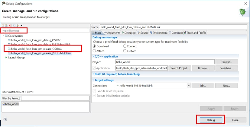
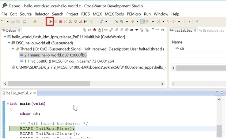
- The debugger downloads program to the board and Debug perspective appears. The execution halts at the first statement of main()
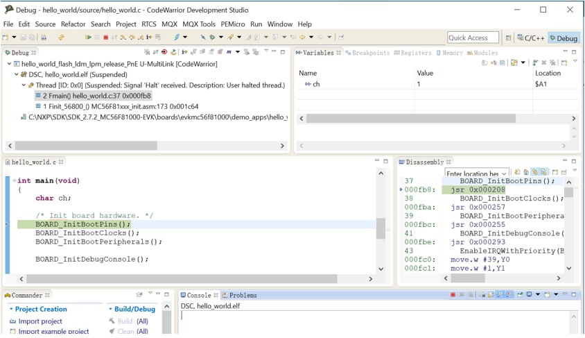
- Open a terminal program and connect to the COM port the board enumerated as. Configure the terminal with these settings:
- 115200 baud rate
- 8 data bits
- No parity
- One stop bit
- No flow control
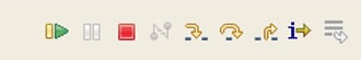
- Start the application by clicking the Resume button
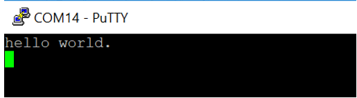
- The hello_world application is now running, and a banner is displayed on the terminal
- Use the controls in the menu bar to pause, step into and step over instructions, and then stop the debugging session by click on the Terminate icon
Install CodeWarrior 11.1
- Launch CodeWarrior 11.1, then go to file -> Import.
- In the list of import source, expand the General tree control and select Existing projects into Workspace. Then click Next
- Select Browse
- Navigate to the example projects downloaded,
SDK_Directory/boards/ evkmc56f81000/demo_apps/hello_world, select codewarrior and click OK. - The selected project appears in the Projects list, click Finish
Note:Don’t modify the project here, otherwise the SDK package will be changed. Don’t send this project to others, because it’s a linked project to your SDK package. See next section about how to create a new standalone project.
Build an Example Application
Now the project appears in the CodeWarrior Project view of the Workbench window. The project have two build configurations with different optimization configuration. ‘flash_ldm_lpm_debug’ is configured as Speed optimization level 1, ‘flash_ldm_lpm_release’ is configured as Speed optimization level 4
- Click the tool bar Debug icon, and select Debug Configuration
- The Debug configurations dialog box appears. expand the CodeWarrior tree control and select the build configuration. Then click Debug
- The debugger downloads program to the board and Debug perspective appears. The execution halts at the first statement of main()
- Open a terminal program and connect to the COM port the board enumerated as. Configure the terminal with these settings:
- 115200 baud rate
- 8 data bits
- No parity
- One stop bit
- No flow control
- Start the application by clicking the Resume button
- The hello_world application is now running, and a banner is displayed on the terminal
- Use the controls in the menu bar to pause, step into and step over instructions, and then stop the debugging session by click on the Terminate icon
Create
Create an application for MC56F81000-EVK
4.1 New project with CodeWarrior
If one or more of the demo application or driver examples sounds interesting, you’re probably wanting to know how you can build and debug yourself. The following guide provides easy, step-by-step instructions on how to open, build and debug an example code using the CodeWarrior IDE.
Running CodeWarrior IDE
- Launch CodeWarrior 11.1, then go to file -> Import.
- In the list of import source, expand the General tree control and select Existing projects into Workspace. Then click Next
- Select Browse
- Navigate to the example projects downloaded,
SDK_Directory/boards/ evkmc56f81000/demo_apps/hello_world, select codewarrior and click OK. - The selected project appears in the Projects list, click Finish
- Start the CodeWarrior IDE.
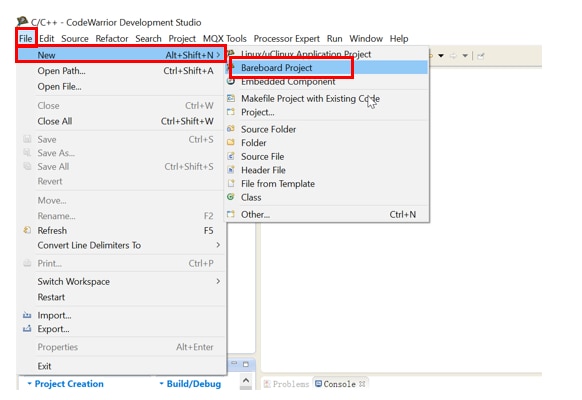
- Create new project
-
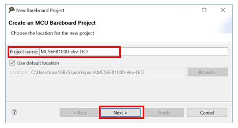
Click File -> New -> Bareboard project, or click
the tool bar New icon and select Bareboard project,
then click Next.
-
Enter the desired project name in the Project name
field. Clear
the Use default location checkbox, click
browse and use the
subsequent dialog box to specify a new project location. Then click
Next.
-
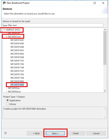
In the device page, expand the tree control and select
56800/E
(DSC) -> MC56F81xxx -> MC56F81868, then click
Next.
-
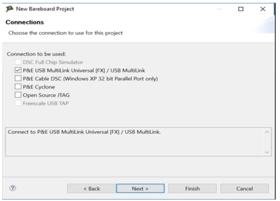
In the Connections page, select the desired connections. If the
on-board debugger is used, select P&E USB Multilink Universal [FX] /
USB Multilink. Then click Next.
-
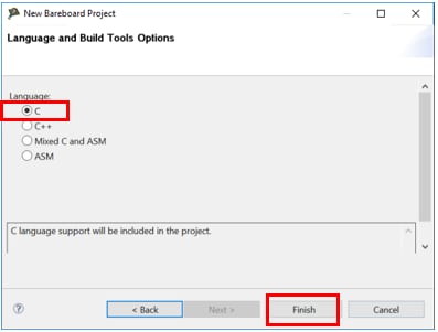
In the Language page, select C language, then Click
Finish, the IDE create the project.
-
Modify the stationary and insert your own code
There are four files in the new project that most in need of modification: main.c, ISR.h, Flash_config.c and Cpu.c.
-
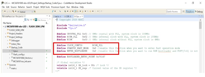
Cpu c contains the routine executed before main. Expand the project
folder and select Project_Settings -> Startup_Code ->
Cpu.c, open
this file.
- 8 MHz internal clock with PLL is used by default, changing CLOCK_CONFIG to choose other clock source.
- Device run in normal mode (50 MHz system clock) by default, setting STARTUP_FAST_MODE will configure the device to run in fast mode (100 MHz system clock).
- Device boot from Flash after reset by default, setting ENTER_BOOTLOADER will enable ROM bootloader. ROM bootloader is executed firstly out of reset.
- Flash_config.c contains a structure variable that configures Bootloader Configuration Area (BCA) and an array variable that configures Flash Configures Field (FCF).
-
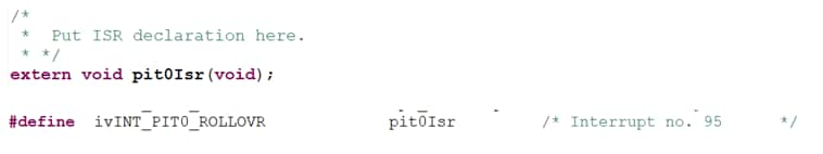
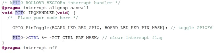
ISR.h contains macros to redefine ISR names. Expand the project
folder and select Project_Headers -> ISR.h, open
this file, then
modify the desired interrupt vector name and add the ISR
declaration. The following picture provides an example of PIT0
interrupt.
-
In main.c, delete the unwanted example codes, but keep below two
lines.
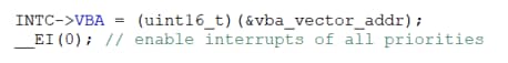
- Insert your own codes.
- Build, compile and run the project as described previously.
- Click the tool bar Debug icon, and select Debug Configuration
- The Debug configurations dialog box appears. expand the CodeWarrior tree control and select the build configuration. Then click Debug
- The debugger downloads program to the board and Debug perspective appears. The execution halts at the first statement of main()
- Open a terminal program and connect to the COM port the board enumerated as. Configure the terminal with these settings:
- 115200 baud rate
- 8 data bits
- No parity
- One stop bit
- No flow control
- Start the application by clicking the Resume button
- The hello_world application is now running, and a banner is displayed on the terminal
- Use the controls in the menu bar to pause, step into and step over instructions, and then stop the debugging session by click on the Terminate icon
Note:Don’t modify the project here, otherwise the SDK package will be changed. Don’t send this project to others, because it’s a linked project to your SDK package. See next section about how to create a new standalone project.
When a bare-mental project is preferred, use the CodeWarrior new project wizard to create a new project, or copy an example code in ‘MC56F81000-EVK Demo Examples’ and modify it. Now, let’s use CodeWarrior to show how to create a bareboard project and edit on it.
Use CodeWarrior IDE to create a new project
Build an Example Application
Now the project appears in the CodeWarrior Project view of the Workbench window. The project have two build configurations with different optimization configuration. ‘flash_ldm_lpm_debug’ is configured as Speed optimization level 1, ‘flash_ldm_lpm_release’ is configured as Speed optimization level 4
Running CodeWarrior IDE
- Launch CodeWarrior 11.1, then go to file -> Import.
- In the list of import source, expand the General tree control and select Existing projects into Workspace. Then click Next
- Select Browse
- Navigate to the example projects downloaded,
SDK_Directory/boards/ evkmc56f81000/demo_apps/hello_world, select codewarrior and click OK. - The selected project appears in the Projects list, click Finish
Note:Don’t modify the project here, otherwise the SDK package will be changed. Don’t send this project to others, because it’s a linked project to your SDK package. See next section about how to create a new standalone project.
Build an Example Application
Now the project appears in the CodeWarrior Project view of the Workbench window. The project have two build configurations with different optimization configuration. ‘flash_ldm_lpm_debug’ is configured as Speed optimization level 1, ‘flash_ldm_lpm_release’ is configured as Speed optimization level 4
- Click the tool bar Debug icon, and select Debug Configuration
- The Debug configurations dialog box appears. expand the CodeWarrior tree control and select the build configuration. Then click Debug
- The debugger downloads program to the board and Debug perspective appears. The execution halts at the first statement of main()
- Open a terminal program and connect to the COM port the board enumerated as. Configure the terminal with these settings:
- 115200 baud rate
- 8 data bits
- No parity
- One stop bit
- No flow control
- Start the application by clicking the Resume button
- The hello_world application is now running, and a banner is displayed on the terminal
- Use the controls in the menu bar to pause, step into and step over instructions, and then stop the debugging session by click on the Terminate icon
4.2 Clone an example project with MCUXpresso Config Tool
Option A: Use the MCUXpresso Config Tool to clone an existing MCUXpresso SDK example project.
1. Clone a project by MCUXpresso Config Tool
The following steps will guide you through cloning the example project with MCUXpresso Config Tool.
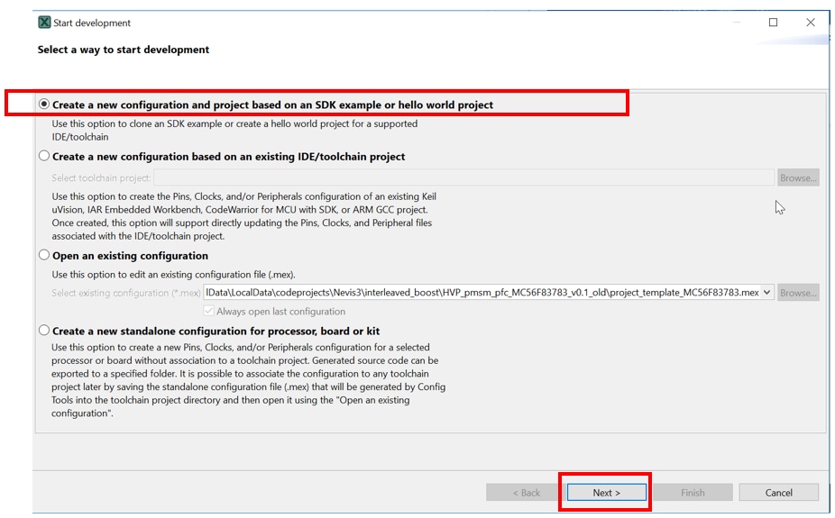
- Open the MCUXpresso Config Tool.
-
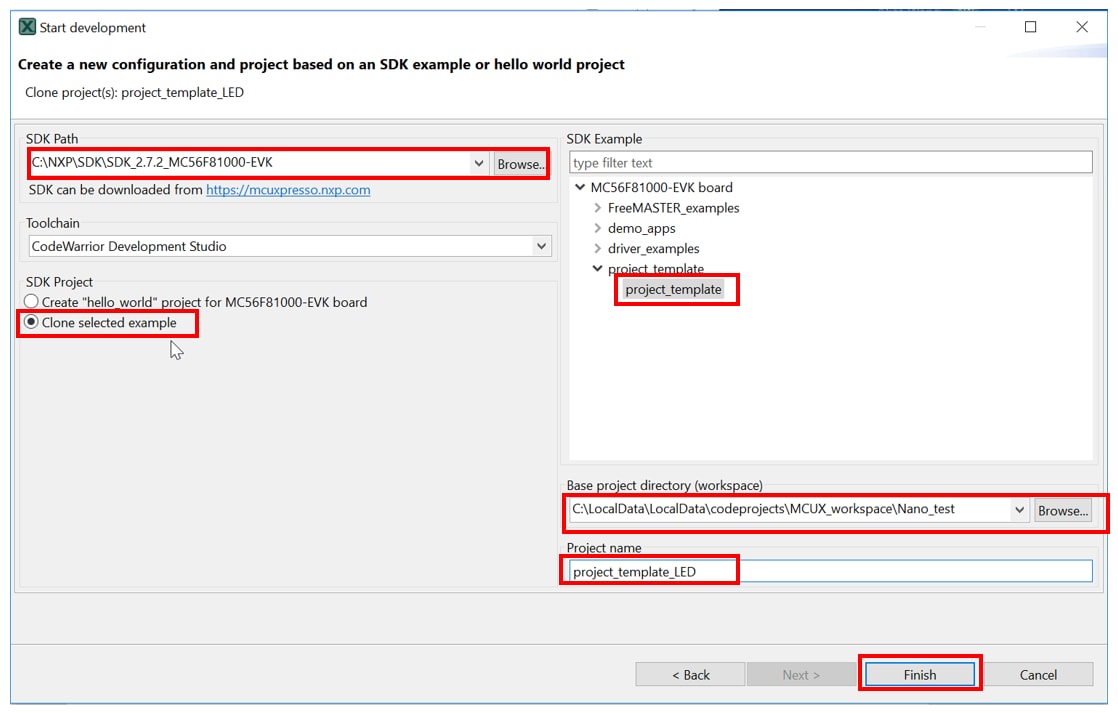
Select the Create a new configuration and project based on an SDK
example
or hello world project radio button from the Start development
window.
Alternatively, you can select the option by choosing File ->
New from the
Main Menu. Then click Next.
-
On the next screen, click Browse… to select the location of
the
MCUXpresso SDK that you had unzipped earlier, then select the project to
clone. In this guide, we use the project template. You can
then also specify
where to store this project and the project name. Then click
finish.
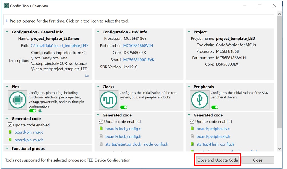
-
Click Close and Update Code.
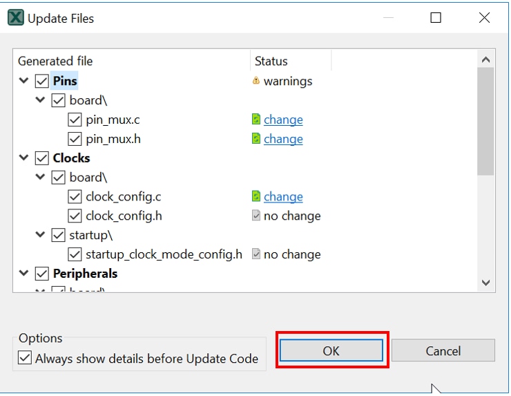
-
Click OK.
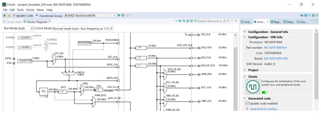
-
A new project is cloned and the Clocks tool appears as default.
- After configuration, open the project with CodeWarrior. Import, build, and run the project as done in the previous section.
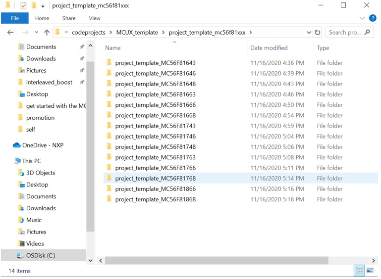
Option B: Copy an template project in ‘ Project Template MC56F81xxx ’ and modify it. The template projects are extracted from related packages and contains all the necessary drivers.
2. Copy a template project
-
Download the project template package and unzip. There are template projects
for any part of 56F81xxx.
-
Launch CodeWarrior 11.1, then go to file -> Import.
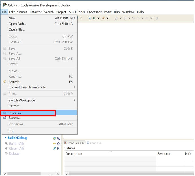
-
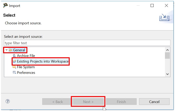
In the list of import source, expand the General tree
control and select Existing projects into Workspace. Then
click Next.
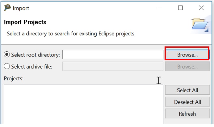
-
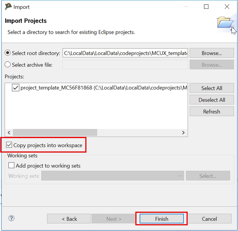
Select Browse…, navigate to the template projects
downloaded and select.
-
The selected project appears in the Projects list, and select ‘Copy
projects into workspace’, so that a new project is created and
the template
won’t be changed, then click Finish.
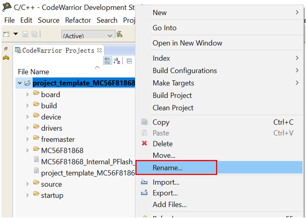
-
Now the project appears in the CodeWarrior Project view of the Workbench
window. Change the project name by right clicking the project name and
select Rename…
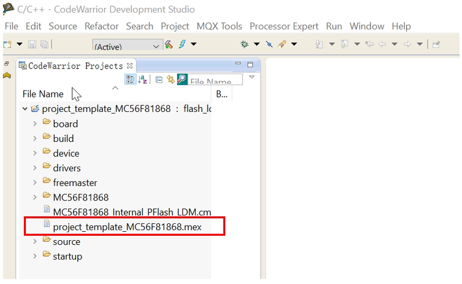
-
Open the Config Tool by double clicking ‘project_template_MC56F81868.mex’
and modify.
4.3 Use the Clock Tools
Now, let’s use the clocks tool that’s part of the MCUXpresso Config Tool to change the clock settings.
1. Use Clocks Tool
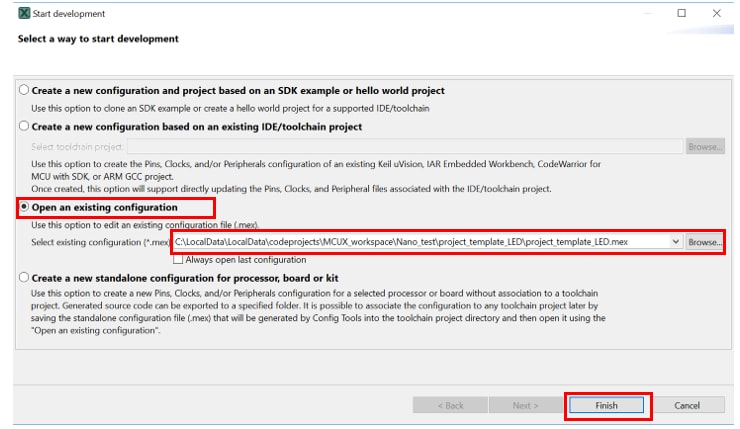
- Open the MCUXpresso Config Tool:
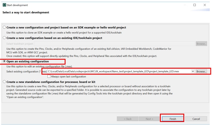
- Double click the ‘mex’ file in the project folder
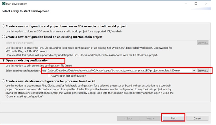
- Open the MCUXpresso Config Tool program, in the wizard that comes up, select the ‘Open an existing configuration’ radio button, and click Browse… to select the project that you want to open, then click Finish
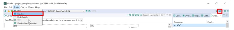
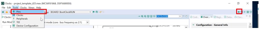
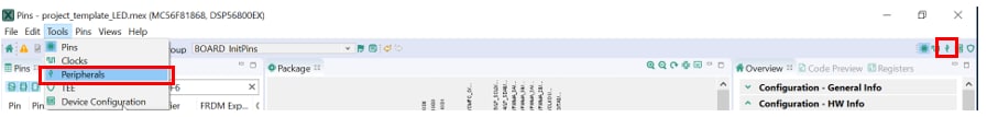
- Open the Clocks Tool by selecting Tools->clocks from the toolbar, or by selecting the Clocks button from the menu bar
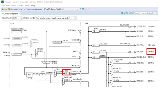
- Use the clocks tool to modify the system clock. The template project configures the chip runs in normal mode, uses internal 8 MHz OSC as the clock source, and enables PLL to generate the 50 MHz BUS_CLK
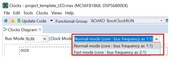
- Change the clock mode by clicking on the Clock Mode check box and selecting the desired mode
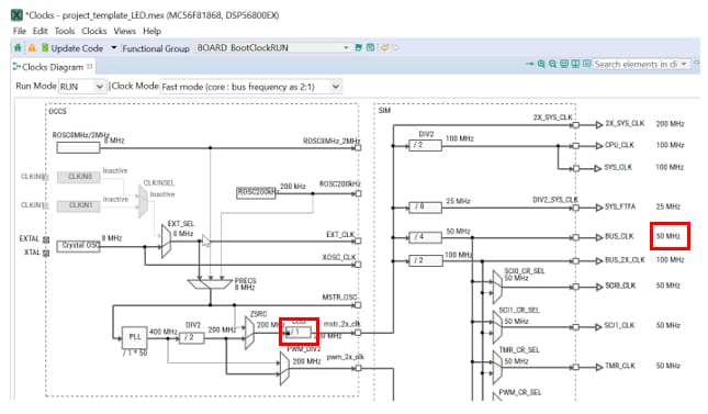
- If fast mode is selected, the BUS_CLK would be 25 MHz under current clock divider. Change COD from 2 to 1 to generate the 50 MHz BUS_CLK and 100 MHz SYS_CLK.
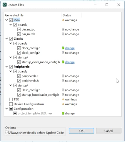
- After configuration, it’s time to implement these changes into the project by exporting the new updated clock files that are generated by Clocks tool. Click on the Update Code in the menu bar.

- The screen that pops up will show the files that are changing, and you can click on ‘change’ to see the difference between the current file and the new file generated. Then click OK to overwrite the new files into your project.
4.4 Use the Pins Tool
Next use the Pins tool that is part of the MCUXpresso Config Tool to show how to add a new GPIO pin to your project to blink an LED.
1. Use the Pins Tool
- Open the MCUXpresso Config Tool:
- Double click the ‘mex’ file in the project folder.
- Open the MCUXpresso Config Tool program, in the wizard that comes up, select the ‘Open an existing configuration’ radio button, and click Browse… to select the project that you want to open, then click Finish.
- Open the Pins Tool by selecting Tools->Pins from the toolbar, or by selecting the Pins button from the menu bar. The pins tool now display the pin configuration for the template project.
- Use the pins tool to modify the LED routed pin:
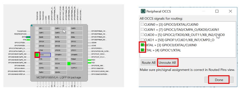
- In the current configuration, GPIOC0 and C1 are routed as EXTAL and XTAL, GPIOC11 and C12 are routed as TXD1 and RXD1 (routed pins have a check in a green box next to the pin name, and the functions selected for each routed pin are shown).
- Disable OCCS routed pins. Click the green box next to OCCS, in the wizard that comes up, uncheck EXTAL and XTAL, or click the Unroute All. Then click Done. The pins will then be disabled and disappear from the Routed Pins list.
- Disable QSCI1 routed pins as last step.
-
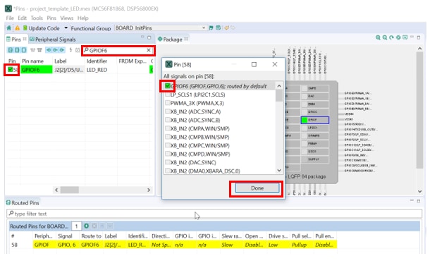
Route GPIOF6 as a GPIO for LED D5
Option A: Search GPIOF6 in the Pins view, click the box next to pin number and select GPIOF6 in the pop-up window, then click Done. The pin will then appear in the Routed Pins list.
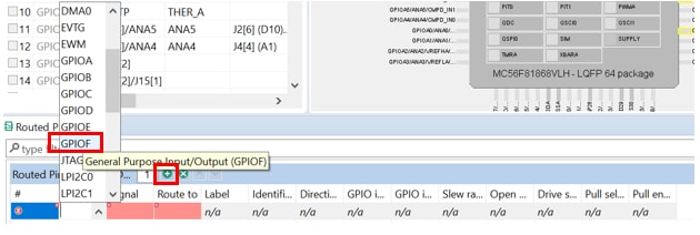
Option B: Add a new row directly in Routed Pins window, click the peripheral box and select GPIOF, then select GPIO,6 in the signal box.
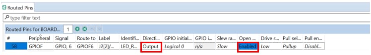
- Configure GPIOF6 properties.
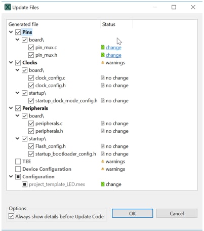
- Now it’s time to implement these changes into the project by exporting the new updated files that are generated by the Pins tool. Click on the Update Code in the menu bar.

- The screen that pops up will show the files that are changing, and you can click on ‘change’ to see the difference between the current file and the new file generated. Then click OK to overwrite the new files into your project.
4.5 Use the Peripherals Tool
Next use the Peripheral tool that is part of the MCUXpresso Config Tool to show how to configure a PIT for LED blinking frequency control.
Use Peripheral Tool
- Open the MCUXpresso Config Tool:
- Double click the ‘mex’ file in the project folder.
- Open the MCUXpresso Config Tool program, in the wizard that comes up, select the ‘Open an existing configuration’ radio button, and click Browse… to select the project that you want to open, then click Finish.
- Open the Clocks Tool by selecting Tools->Peripherals from the toolbar, or by selecting the Peripherals button from the menu bar.
- Use the peripherals tool to configure PIT0:
-
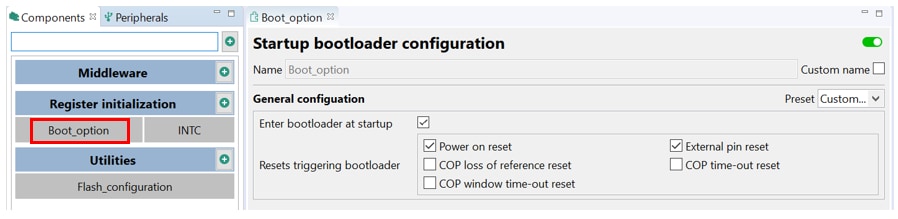
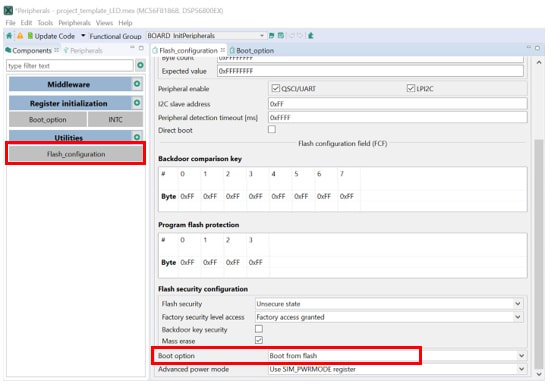
Open Boot_option by double clicking it in the components window. In current configuration, chip boots from Flash. Select the ‘Enter bootloader at startup’, ‘Power on reset’ and ‘External pin reset’ check boxes, chip will boot from ROM at power on reset and pin reset. The BCA and FCF can be changed in Flash_configuration.
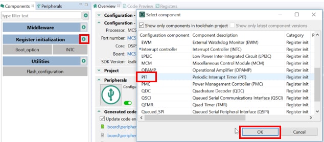
- Add a PIT by clicking the Add button and select PIT, then click OK.
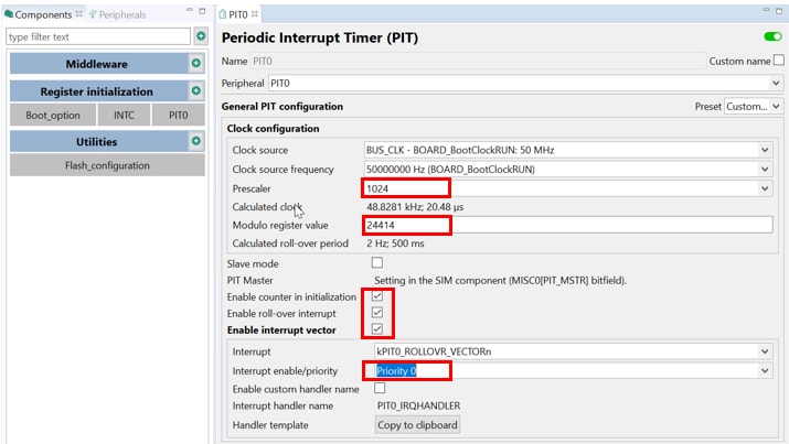
- Now PIT0 appears in the components window and it’s opened. Change PIT0 configuration as the following picture, PIT0 roll-over interrupt is enabled for GPIOF6 flip.
- Now it’s time to implement these changes into the project by exporting the new updated files that are generated by the Periperals tool. Click on the Update Code in the menu bar.

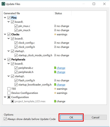
- The screen that pops up will show the files that are changing, and you can click on ‘change’ to see the difference between the current file and the new file generated. Then click OK to overwrite the new files into your project.
- Import the project into CodeWarrior IDE as done in the previous section.
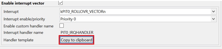
- Open main.c in the project folder and add the interrupt routine in it by selecting ‘Copy to clipboard’ and pasting.
- Add the GPIOF6 flip code into PIT0 rollover interrupt.
- Build and download the project as done in the previous section.
- Run the application. You should now see the red LED is flashing.
- Terminate the debug session. Push the reset button SW1, after waiting several seconds (bootloader timeout), you should now see the red LED starts flashing.
Learn
Explore beyond the MC56F81000-EVK by integrating other NXP solutions and software to your project and interact with our worldwide design community.
5.1 Motor Control
MC56F81000-EVK form-factor compatible with the LVPMSM and LVBLDC motor control platform, adds the motor control capabilities. Find out more at FRDM-MC-LVPMSM and FRDM-MC-LVBLDC.
5.2 DSC and MCUXpresso Communities
Connect with other engineers and get expert advice on designing with DSC and MCUXpresso Software and Tools. Join the community discussion in one of our two dedicated communities: DSC community or MCUXpresso Software and Tools Community.
Tera Term Tutorial
Tera Term Tutorial
Tera Term is a very popular open source terminal emulation application. This program can be used to display information sent from your NXP development platform's virtual serial port.
- Download Tera Term from SourceForge. After the download, run the installer and then return to this webpage to continue.
- Launch Tera Term. The first time it launches, it will show you the following dialog. Select the serial option. Assuming your board is plugged in, there should be a COM port automatically populated in the list.
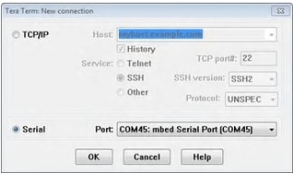
- Configure the serial port settings (using the COM port number identified earlier) to 115200 baud rate, 8 data bits, no parity and 1 stop bit. To do this, go to Setup -> Serial Port and change the settings.
- Verify that the connection is open. If connected, Tera Term will show something like below in its title bar
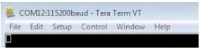
- You're ready to go
PuTTY Tutorial
PuTTY Tutorial
PuTTY is a popular terminal emulation application. This program can be used to display information sent from your NXP development platform's virtual serial port.
- Download PuTTY using the button below. After the download, run the installer and then return to this webpage to continue.
- PuTTY by either double-clicking on the
*.exefile you downloaded or from the Start menu, depending on the type of download you selected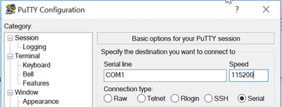
- Click Open to open the serial connection. Assuming the board is connected and you entered the correct COM port, the terminal window will open. If the configuration is not correct, PuTTY will alert you
- You're ready to go
Support
Forums
Learn more about the MC56F81000-EVK with design tips, training documents, and the NXP Community. If you need additional help, contact NXP Support.
Communities
Connect with other engineers and get expert advice on designing with DSC and MCUXpresso Software and Tools. Join the community discussion in one of our two dedicated communities: DSC community or MCUXpresso Software and Tools Community.
On this page
- 2.1
Install your toolchain
- 2.2
Jump-Start Your Design with the MCUXpresso SDK
- 2.3
FreeMASTER
- 2.4
MCUXpresso Config Tools
- 2.5
Serial terminal