Getting Started with the KITFS24SKTFDMEVM Evaluation Board
Contents of this document
-
Out of the Box
-
Get Hardware
-
Configure Hardware
Sign in to save your progress. Don't have an account? Create one.
Purchase your KITFS24SKTFDMEVM
1. Out of the Box
The NXP analog product development boards provide an easy-to-use platform for evaluating NXP products. The boards support a range of analog, mixed-signal and power solutions. They incorporate monolithic integrated circuits and system-in-package devices that use proven high-volume technology. NXP products offer longer battery life, a smaller form factor, reduced component counts, lower cost and improved performance in powering state-of-the-art systems.
This page will guide the user through the process of setting up and using the KITFS23SKTFDMEVM board.
1.1 Kit Contents and Packing List
The KITFS24SKTFDMEVM kit contents include:
- Assembled and tested evaluation board with preprogrammed S32K144 microcontroller in an antistatic bag
- USB-STD A to USB-B-mini cable
- Four connectors, terminal block plug, two positions, 3.81 mm pitch between pins
- One connector, terminal block plug, three positions, 3.81 mm pitch between pins
- Jumpers mounted on the board
1.2 Additional Hardware
In addition to the kit contents, the following hardware is necessary or beneficial when working with this kit:
- A power supply with a range up to 40 V and a current limit set initially to 1 A
1.3 Minimum System Requirements
This evaluation board requires a Windows PC workstation.
- USB-enabled computer with Windows 7 or Windows 10
- FTDI USB serial port driver (for FT230X Basic UART device)
1.4 Software
Installing the software is necessary to work with the KITFS24SKTFDMEVM evaluation board. All listed software is available on the evaluation board's information at the Analog Toolbox page.
- NXP GUI for automotive SBC family installation package - latest version
2. Get Hardware
2.1 Board Features
- Phoenix (3.81 mm) male connector for power supply input
- Phoenix (3.81 mm) male connectors for HVBUCK and HVLDO
- Phoenix (3.81 mm) male connectors for CAN communication
- Ignition key switch
- Embedded USB connection for easy connection to the NXP GUI (access to SPI/CAN bus, I/Os, RSTB, LIMP0, INTB, Debug, AMUX, regulators, registers, OTP emulation and programming)
- LEDs that indicate signal or regulator status
- Support OTP fuse capabilities
2.2 Board Description
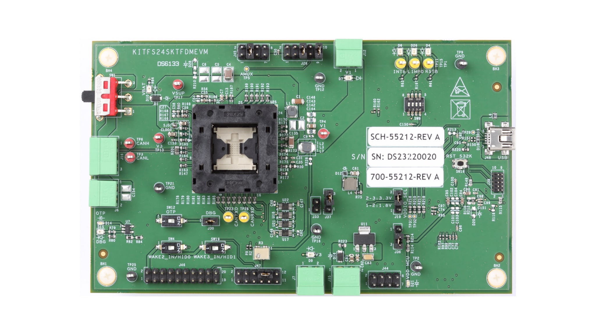
The KITFS24SKTFDMEVM kit provides an integrated platform for evaluating designs based on NXP’s FS2400 SBC.
The kit hardware consists of the KITFS24SKTFDMEVM evaluation board with an embedded S32K144 microcontroller, and the USB cable required to connect the board to the PC.
2.3 Board Components
Overview of the KITFS24SKTFDMEVM board
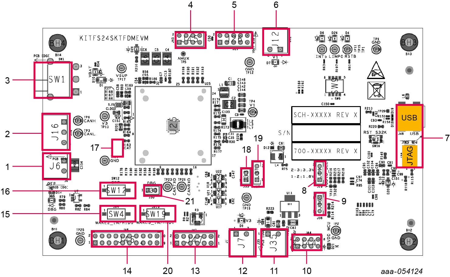
| Number | Description |
|---|---|
| 1 | CAN Phoenix connector |
| 2 | VBAT Phoenix connector |
| 3 | VBAT three position switch
|
| 4 | V1 power supply Phoenix connector |
| 5 | USB connectors (JTAG for MCU flash; S32K144 for NXP GUI control) |
| 6 | Optical probe connectors |
| 7 | Communication debug connector (SPI and CAN) |
| 8 | ALT_VBAT Phoenix connector (to supply MCU or VDDIO from a supply other than USB) |
| 9 | FS2400 signals debug connector |
| 10 | WAKE3/HID1 control switch |
| 11 | WAKE2/HID0 control switch |
| 12 | OTP mode control switch |
| 13 | Jumper to set DBG pin voltage to 0 V (if opened) or to 4.7 V/7.95 V (if closed) |
| 14 | Jumper to supply VBAT to the external LDO providing 5 V |
| 15 | 5 V selection (USB or external LDO) |
| 16 | P_VAR net voltage selection (1.8 V or 3.3 V) |
| 17 | S32K144 supply selection |
| 18 | V3 power supply Phoenix connector |
3. Configure Hardware
This section gives guidance on how to set up and run the KITFS24SKTFDMEVM evaluation board and GUI.
3.1 Set up the KITFS24SKTFDMEVM
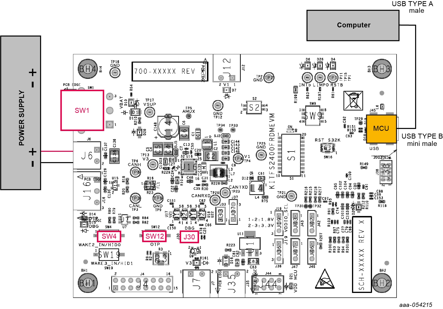
The procedure for setting up the KITFS24SKTFDMEVM board is as follows:
- Make sure that the board has the jumpers and switches configured in their default positions. The default debug configuration enables the board to be fully controlled by the S32K144 MCU (via SPI) and the GUI. Kit featured components shows the default jumpers and switches configurations
- Connect the power supply to
J6(Phoenix connector - 3.81 mm). The power supply should be set to a nominal value of 14 V - Make sure that the USB cable between the board and the PC is securely connected. This connection is critical because the USB port serves as a communication channel between the PC and the S32K144 MCU onboard and provides voltages and references to some onboard circuits
- Place
SW1in top position (2-3)
3.2 Connect the KITFS24SKTFDMEVM to the GUI
The procedure for connecting the KITFS24SKTFDMEVM to the GUI is as follows:
- To launch the NXP GUI application, see UM12015, KITFS24SKTFDMEVM User Manual
- In the USB and Device Status bar at the bottom of the GUI window, the state message should display "DISCONNECTED" when the USB cable is plugged in, but communication has not yet been established between the S32K144 MCU and the FS24xx SBC
- To establish communication between the S32K144 MCU and the FS24xx SBC and allow the GUI to take control, click Start in the Connection toolbar in the top left corner of the GUI window. Once the communication is established, the state message becomes "CONNECTED"
State Disconnected: USB cable plugged in, communication not established yet
State Not Detected: USB cable not plugged in
State Connected: USB cable plugged in, communication established

Design Resources
Additional References
In addition to the KITFS24SKTFDMEVM product page, you may also want to visit: