Getting Started with the KITFS23SKTEVM Evaluation Board
Contents of this document
-
Out of the Box
-
Get to Know the Hardware
-
Install Software
-
Configure Hardware
Sign in to save your progress. Don't have an account? Create one.
Purchase your KITFS23SKTEVM
1. Out of the Box
The NXP analog product development boards provide an easy-to-use platform for evaluating NXP products. The boards support a range of analog, mixed-signal and power solutions. They incorporate monolithic integrated circuits and system-in-package devices that use proven high-volume technology. NXP products offer longer battery life, a smaller form factor, reduced component counts, lower cost, and improved performance in powering state-of-the-art systems.
This page will guide you through the process of setting up and using the KITFS23SKTEVM board.
1.1 Kit Contents and Packing List
The KITFS23SKTEVM kit contents include:
- Assembled and tested evaluation board with preprogrammed S32K144 microcontroller in an anti-static bag
- 3.0 ft USB-STD A to USB-B-micro cable
- Four connectors, terminal block plug, two positions, straight, 3.81 mm
- Four connectors, terminal block plug, three positions, straight, 3.81 mm
- Jumpers mounted on board
1.2 Additional Hardware
In addition to the kit contents, the following hardware is necessary or beneficial when working with this kit:
- One power supply with a range up to 40 V
1.3 Minimum System Requirements
This evaluation board requires a Windows PC workstation.
- USB-enabled computer with Windows 7 or Windows 10
- FTDI USB serial port driver (for FT230X Basic UART device)
1.4 Software
Installing software is necessary to work with the KITFS23SKTEVM evaluation board. All listed software is available on the evaluation board's information page at the FS23 Safety SBC Programming Socket Board.
- NXP GUI for automotive SBC family installation package - latest version
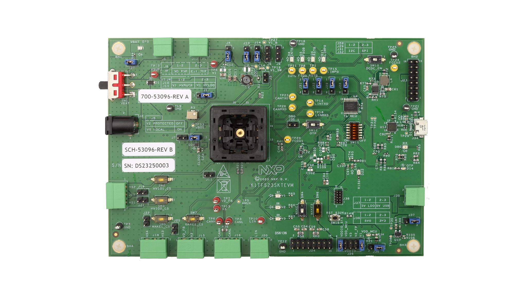
2. Get to Know the Hardware
2.1 Board Features
- Phoenix (3.81 mm) male connector or Jack connector for power supply input
- Phoenix (3.81 mm) male connectors for HVBUCK and HVLDOs
- Phoenix (3.81 mm) male connectors for CAN and LIN communication
- Phoenix (3.81 mm) male connectors for high-side drivers
- Selectable Debug mode, test mode and normal mode with switches and jumpers to power up the device in different modes
- INTB, RSTB, FS0B, LIMP0, FCCU pins
- Embedded USB to I2C/SPI protocol for easy connection to software GUI through S32K144 MCU
- Red and green LEDs to indicate signal or regulator status
- Blue LED to indicate that OTP 8.0 V burning voltage is set
- Header connectors for I/O configuration
- Advanced system monitoring via S32K144 MCU
2.2 Board Description
The KITFS23SKTEVM board is a socketed board supporting FS2300 fail-safe system basis chip with three LDOs and FS2320 fail-safe system basis chip with one SMPS and two LDOs. In this document, "FS23xx" refers to these supported devices.
The KITFS23SKTEVM enables development on FS23xx Body and Comfort SBC family of devices. This document covers connecting the hardware, installing the NXP GUI software, configuring the environment and using the kit. It includes guidance on how to use the registers, try OTP configurations and burn the part.

3. Install Software
The development kit uses NXP GUI for Automotive PMICs Families
3.1 Flashing or Updating the GUI Firmware
The KITFS23xxxEVM is delivered with the GUI firmware flashed in the board’s MCU.
3.2 Installing GUI Software Package
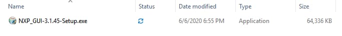
To install the FS23 NXP GUI, download or obtain the NXP GUI package, unzip 1- NXP_GUI_Setup folder:

Then, double-click NXP_GUI_version-Setup.exe and follow the instructions.
To install the application on Windows PC, proceed with the following pop-up windows:


Select the following options before completing the installation of the setup:
- Run NXP_GUI
- Show Readme
Select Finish to complete the installation.

When the installation is finished, you can find the application by searching for NXPGUI in the windows search bar. Click to launch.
4. Configure Hardware
This section gives guidance on how to set up and run KITFS23SKTEVM evaluation board and GUI.
4.1 Set up the KITFS23SKTEVM
The procedure for setting up the KITFS23SKTEVM board is as follows:
- Make sure the board has the jumpers and switches configured in their default positions. The default debug configuration enables the board to be fully controlled by the S32K144 MCU (via I2C) and the GUI
- Connect the power supply to
J6(Phoenix connector - 3.81 mm). The power supply should be set to a nominal value of 14.0 V. Or connect the power supply toJ2(Jack connector) via a 14.0 V battery - Make sure the USB cable between the board and the PC is securely connected. This connection is critical because the USB port serves as a communication channel between the PC and the S32K144 MCU onboard, and provides voltages and references to some onboard circuits
- Place
SW1to positionSW1-3if the power supply is connected toJ6. Or placeSW1to positionSW1-1if the power supply is connected toJ2
4.2 Connect the KITFS23SKTEVM to the GUI
The procedure for connecting the KITFS23SKTEVM to the GUI is as follows:
- To launch the NXP GUI application, see UM11882, KITFS23SKTEVM User Manual
- In the USB and Device Status bar at the bottom of the GUI window, the state message should display "DISCONNECTED" when the USB cable is plugged in, but communication has not yet been established between the S32K144 MCU and the FS23xx SBC
- To establish communication between the S32K144 MCU and the FS23xx SBC and allow the GUI to take control, click Start in the Connection toolbar in the top left corner of the GUI window. Once the communication is established, the state message becomes "CONNECTED"
State Disconnected: USB cable plugged in, communication not established yet
State Not Detected: USB cable not plugged in
State Connected: USB cable plugged in, communication established

Design Resources
Additional References
In addition to our FS23, Safety System Basis Chip (SBC) Family with Power Management, CAN and LIN page, you may also want to visit: