Getting Started with the FRDMGD3162RPEVM Evaluation Board
Contents of this document
-
Out of the Box
-
Get Hardware
-
Get Software
Sign in to save your progress. Don't have an account? Create one.
Purchase your FRDMGD3162RPEVM
1. Out of the Box
The NXP analog product development boards provide an easy-to-use platform for evaluating NXP products. The boards support a range of analog, mixed-signal and power solutions. They incorporate monolithic integrated circuits and system-in-package devices that use proven high-volume technology. NXP products offer longer battery life, a smaller form factor, reduced component counts, lower cost and improved performance in powering state-of-the-art systems.
This page will guide you through the process of setting up and using the FRDMGD3162RPEVM board.
1.1 Kit Content and Packing List
The FRDMGD3162RPEVM kit contents include:
- Assembled and tested FRDMGD3162RPEVM board in an antistatic bag
- 3.3 to 5.0 V translator board (KITGD316xTREVB) connected to FRDM-KL25Z MCU board
- USB cable, type A male/type mini B male, 3 ft
- Quick start guide
1.2 Required Equipment
To use this kit, you need:
- Compatible SiC RoadPak module
- DC link capacitor compatible with the SiC RoadPak module
- 1.27 mm jumpers for configuration (included with kit)
- 30 to 50 µH, high-current air core inductor for double-pulse testing
- HV power supply with protection shield and hearing protection
- 20 V, 1.0 A DC power supply
- 500 MHz 2.5 GS/s 4-channel oscilloscope
- Rogowski coil, AC current probe (smaller diameter)
- Isolated high-voltage probes
- Digital voltmeter
2. Get Hardware
2.1 Board Features
- Capability to connect to Hitachi RoadPak module for half-bridge evaluations
- Adjustable negative VEE gate low drive level (–1.5 to –7.5 V DC)
- Adjustable VCC gate high drive level (10 to 25 V DC)
- Jumper configurable for disabling dead-time fault protection when short-circuit testing
- Easy access power, ground and signal test points
- Easy to install and use FlexGUI for interfacing via SPI through PC; software includes double-pulse and short-circuit testing capability
- DC link bus voltage monitor on low-side driver via AMUXIN and AOUT
- Negative temperature coefficient (NTC) connection and configurable for monitoring module temperature
2.2 Board Description
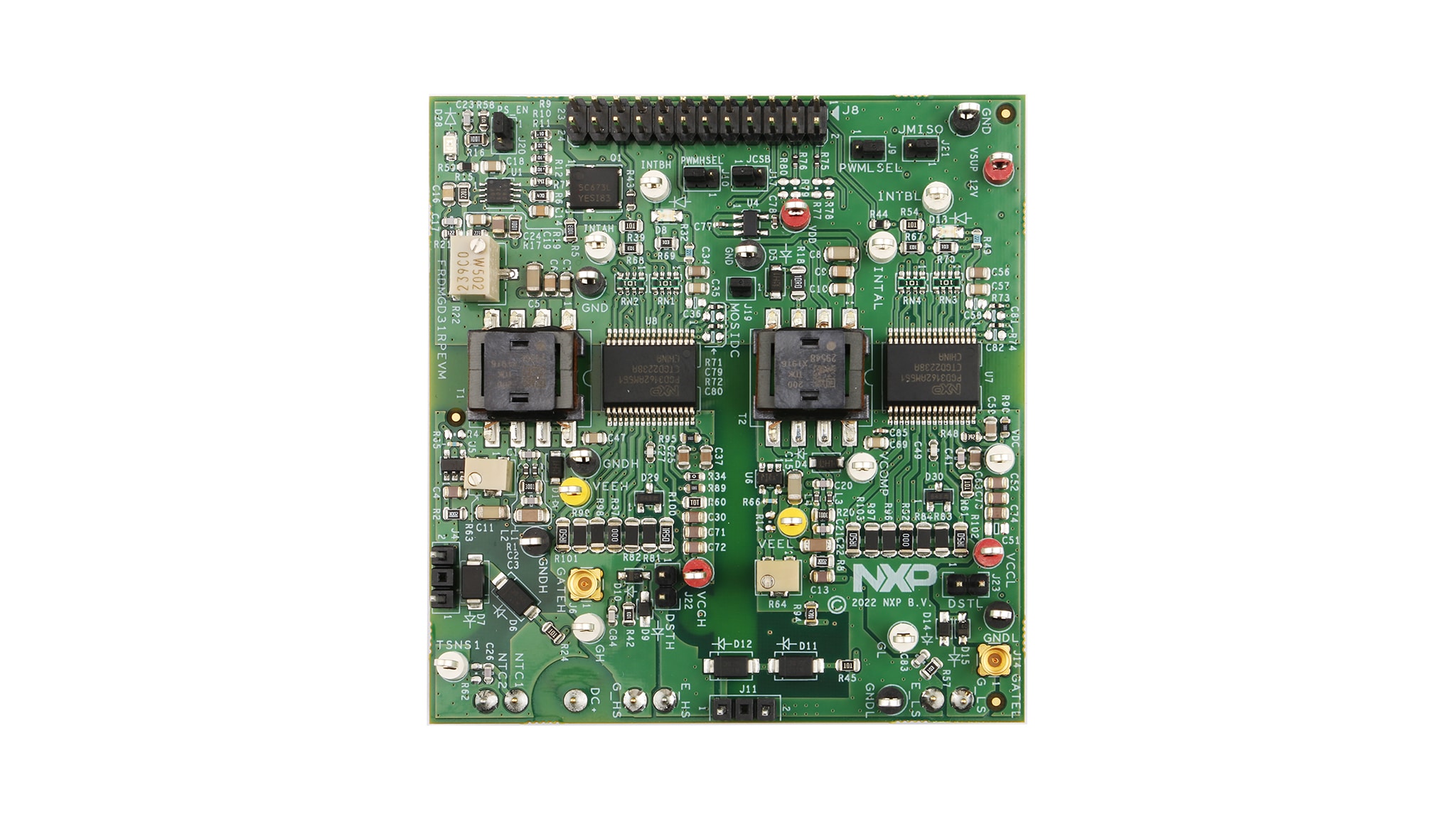
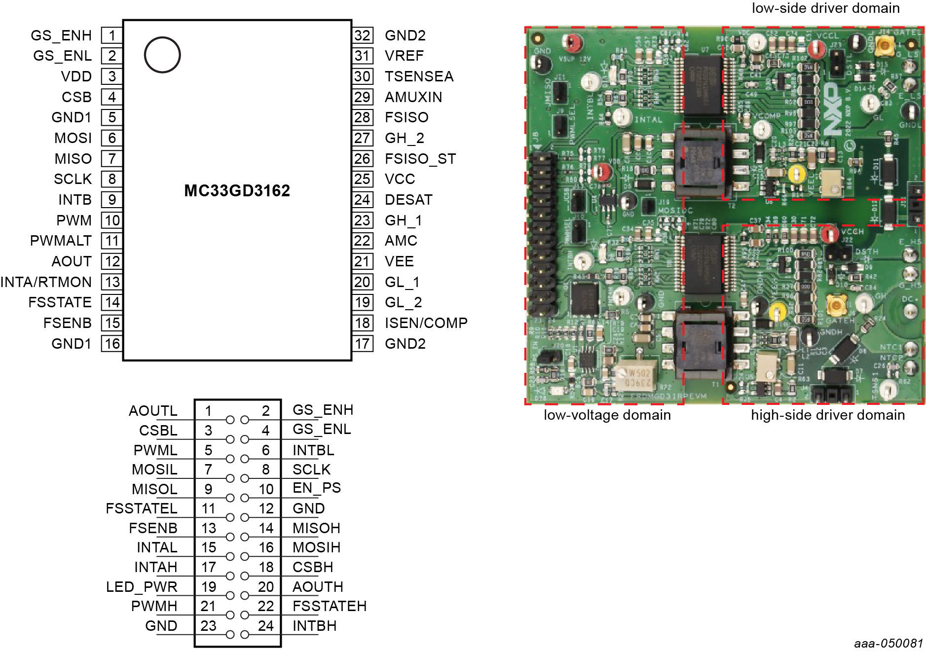
The FRDMGD3162RPEVM is a half-bridge evaluation kit populated with two GD3162 single-channel gate drive devices. The kit includes the Freedom KL25Z microcontroller hardware for interfacing a PC installed with FlexGUI software for communication to the serial peripheral interface (SPI) registers on the GD3162 gate drive devices in either daisy chain or standalone configuration.
The KITGD316xTREVB translator board is used to translate 3.3 V signals to 5.0 V signals between the MCU and GD3162 gate drivers. The evaluation kit can be connected to a compatible insulated-gate bipolar transistor (IGBT) or SiC MOSFET module for half-bridge evaluations and applications development.

3. Get Software
3.1 Installation and Use of Software Tools
Software for the FRDMGD3162RPEVM is distributed with the FlexGUI tool (available on NXP). Necessary firmware comes pre-installed on the FRDM-KL25Z with the kit.
Even if the user intends to test with other software or PWM, it is recommended to install the software for the FRDMGD3162RPEVM as a backup or to help debugging.