Getting Started with the EVBMA777T and EVBMA8420T
Contents of this document
-
Out of the Box
-
Get Hardware
-
Configure Hardware
Sign in to save your progress. Don't have an account? Create one.
Purchase your EVBMA777T2
1. Out of the Box
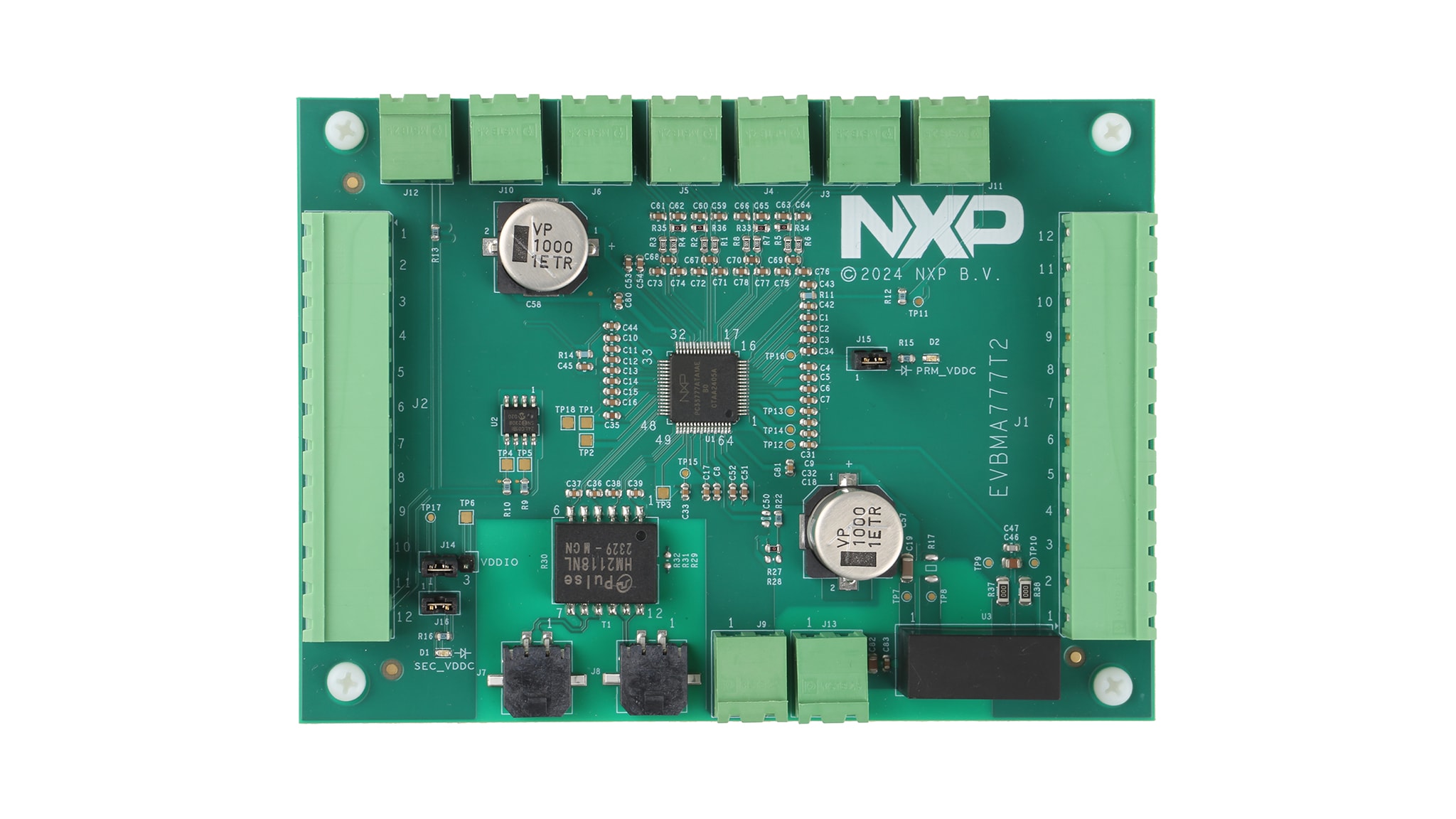
The EVBMA777T; EVBMA8420T allows the user to exercise all the functions of the MC33777A; BMA8420 battery junction box controller IC. Most pins of the MC33777A; BMA8420 are accessible via a connector. The user can configure the IC to evaluate all use cases.
1.1 Kit Contents and Packing List
The EVBMA777T and EVBMA8420T contents include:
- One electrical transport protocol link (ETPL) communication cable
- One power supply cable
- Four two-position connectors
- Two 12-position connectors
1.2 Additional Hardware
In addition to the kit contents, the following hardware is necessary or beneficial when working with this kit.
- Mandatory +24 V and +100 mA power supply
- Optional voltage sources (to test the measurements)
- Optional power resistors (to test the pyrotechnic switch controller)
- Optional negative temperature coefficient (NTC) resistor (to test temperature measurement)
2. Get the Hardware
2.1 Board Features
The main features of the EVBMA777T and EVBMA8420T are:
- Isolated power supply
- ETPL communication
- LED indicator for supply voltages and operation modes
- Four current measurement inputs
- Two external temperature measurement channels
- All input and outputs of the MC33777A; BMA8420 are accessible with connectors
- Energy reservoir capacitor for pyrotechnic switch control
- EEPROM connected to the MC33777A; BMA8420 in I2C
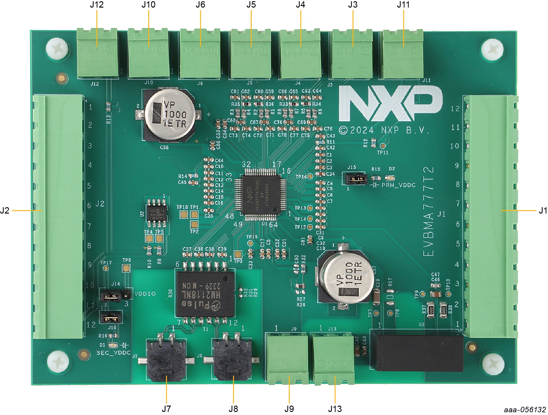
2.2 Connectors
The EVBMA777T; EVBMA8420T has multiple connectors for interfacing a power supply, a controller, or external instruments.
Figure 1 shows the location of the connectors.
| Pin | Connection | Description |
|---|---|---|
Power supply (J13) |
||
J13.1 |
24V+ | positive power supply terminal |
J13.2 |
24V- | power supply isolated ground |
ETPL communication (J7) |
||
J7.1 |
TPL1P | ETPL positive input/output from/to lower node |
J7.2 |
TPL1N | ETPL negative input/output from/to lower node |
ETPL communication (J8) |
||
J8.1 |
TPL2P | ETPL positive input/output from/to upper node |
J8.2 |
TPL2N | ETPL negative input/output from/to upper node |
Primary ISENSE inputs (J3) |
||
J3.1 |
PRM_ISENSEP | primary positive current measurement input |
J3.2 |
PRM_ISENSEN | primary negative current measurement input |
Secondary ISENSE inputs (J4) |
||
| Pin | Connection | Description |
J4.1 |
SEC_ISENSEP | secondary positive current measurement input |
J4.2 |
SEC_ISENSEN | secondary negative current measurement input |
Primary VISENSE inputs (J5) |
||
J5.1 |
PRM_VISENSEP | primary positive current/voltage measurement input |
J5.2 |
PRM_VISENSEN | primary negative current/voltage measurement input |
Secondary VISENSE inputs (J6) |
||
J6.1 |
SEC_VISENSEP | secondary positive current/voltage measurement input |
J6.2 |
SEC_VISENSEN | secondary negative current/voltage measurement input |
Primary external temperature measurement (J11) |
||
J11.1 |
PRM_IO7 | primary external NTC terminal |
J11.2 |
GND | primary external NTC terminal |
Secondary external temperature measurement (J12) |
||
J12.1 |
SEC_IO7 | secondary external NTC terminal |
J12.2 |
GND | secondary external NTC terminal |
Primary I/O and reference voltage (J1) |
||
J1.1 |
PRM_IO6 | primary input/output 6 |
J1.2 |
PRM_IO5 | primary input/output 5 |
J1.3 |
GND | ground |
J1.4 |
PRM_IO4 | primary input/output 4 |
J1.5 |
PRM_IO3 | primary input/output 3 |
J1.6 |
GND | ground |
J1.7 |
PRM_IO2 | primary input/output 2 |
J1.8 |
PRM_IO1 | primary input/output 1 |
J1.9 |
GND | ground |
J1.10 |
PRM_IO0 | primary input/output 0 |
J1.11 |
PRM_VREF2V5 | primary 2.5 V reference |
J1.12 |
PRM_VREF5V0 | primary 5 V reference |
| Pin | Connection | Description |
Secondary I/O and reference voltage (J2) |
||
J2.1 |
SEC_IO6 | secondary input/output 6 |
J2.2 |
SEC_IO5 | secondary input/output 5 |
J2.3 |
GND | ground |
J2.4 |
SEC_IO4 | secondary input/output 4 |
J2.5 |
SEC_IO3 | secondary input/output 3 |
J2.6 |
GND | ground |
J2.7 |
SEC_IO2 | secondary input/output 2 |
J2.8 |
SEC_IO1 | secondary input/output 1 |
J2.9 |
GND | ground |
J2.10 |
SEC_IO0 | secondary input/output 0 |
J2.11 |
SEC_VREF2V5 | secondary 2.5 V reference |
J2.12 |
SEC_VREF5V0 | secondary 5 V reference |
Primary pyrotechnic switch controller (J9) |
||
J9.1 |
PRM_PSCHS | primary high side output of PSC |
J9.2 |
PRM_PSCLS | primary low side output of PSC |
Secondary pyrotechnic switch controller (J10) |
||
J10.1 |
SEC_PSCHS | secondary high side output of PSC |
J10.2 |
SEC_PSCLS | secondary low side output of PSC |
| Connector | Manufacturer | Part number | Mating connector |
|---|---|---|---|
J1, J2 |
Phoenix | 1754630 | 1757116 |
J7, J8 |
Molex | 43650-0213 | 43645-0200 |
J3, J4, J5, J6, J9, J10, J11, J12, J13 |
Phoenix | 1754436 | 1757019 |
2.3 Test points
The EVBMA777T; EVBMA8420T offers multiple test points to access signals close to the MC33777A; BMA8420.
Figure 2. show the location of the test points.
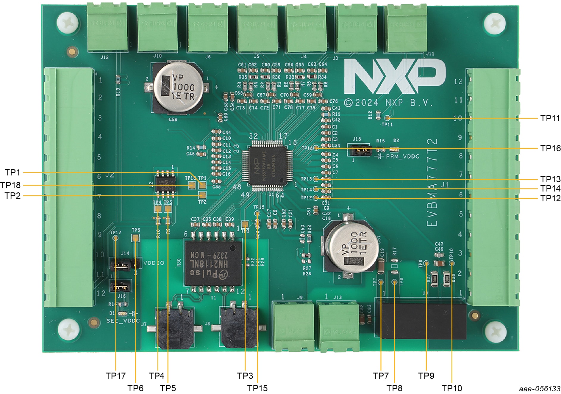
Table 3 list the test points
| Connector | Manufacturer | Part number | Mating connector |
|---|---|---|---|
J1, J2 |
Phoenix | 1754630 | 1757116 |
J7, J8 |
Molex | 43650-0213 | 43645-0200 |
J3, J4, J5, J6, J9, J10, J11, J12, J13 |
Phoenix | 1754436 | 1757019 |
2.4 Jumpers
The EVBMA777T; EVBMA8420T has jumpers to configure MC33777A; BMA8420 signals.
Figure 3. shows the location of the jumpers.
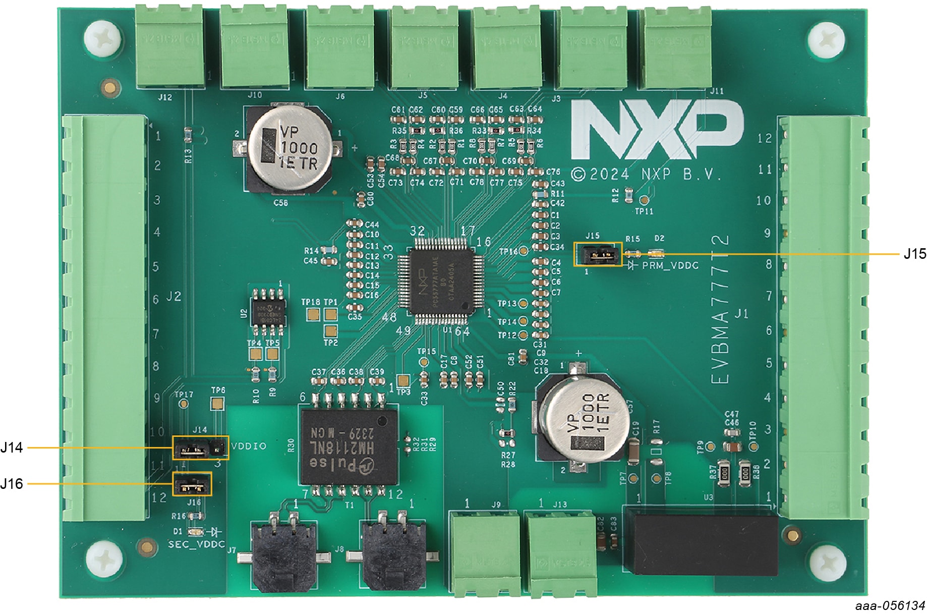
J15 connects an LED to PRM_VDDC of the MC33777A; BMA8420. The LED signals that the device is in active mode. Removing the jumper disables the feature.
J16 connects an LED to SEC_VDDC of the MC33777A; BMA8420. The LED signals that the device is in active mode. Removing the jumper disables the feature.
J14 connects by default VDDIO to SEC_VDDC (jumper between pin 1 and pin 2). The user can power VDDIO with another voltage by moving the jumper (between pin 2 and pin 3) and by applying a voltage on TP6.
3. Configure the Hardware
3.1 Configuring the Hardware
This section describes the typical setup to configure EVBMA777T; EVBMA8420T and evaluate the MC33777A; BMA8420 current measurement feature.
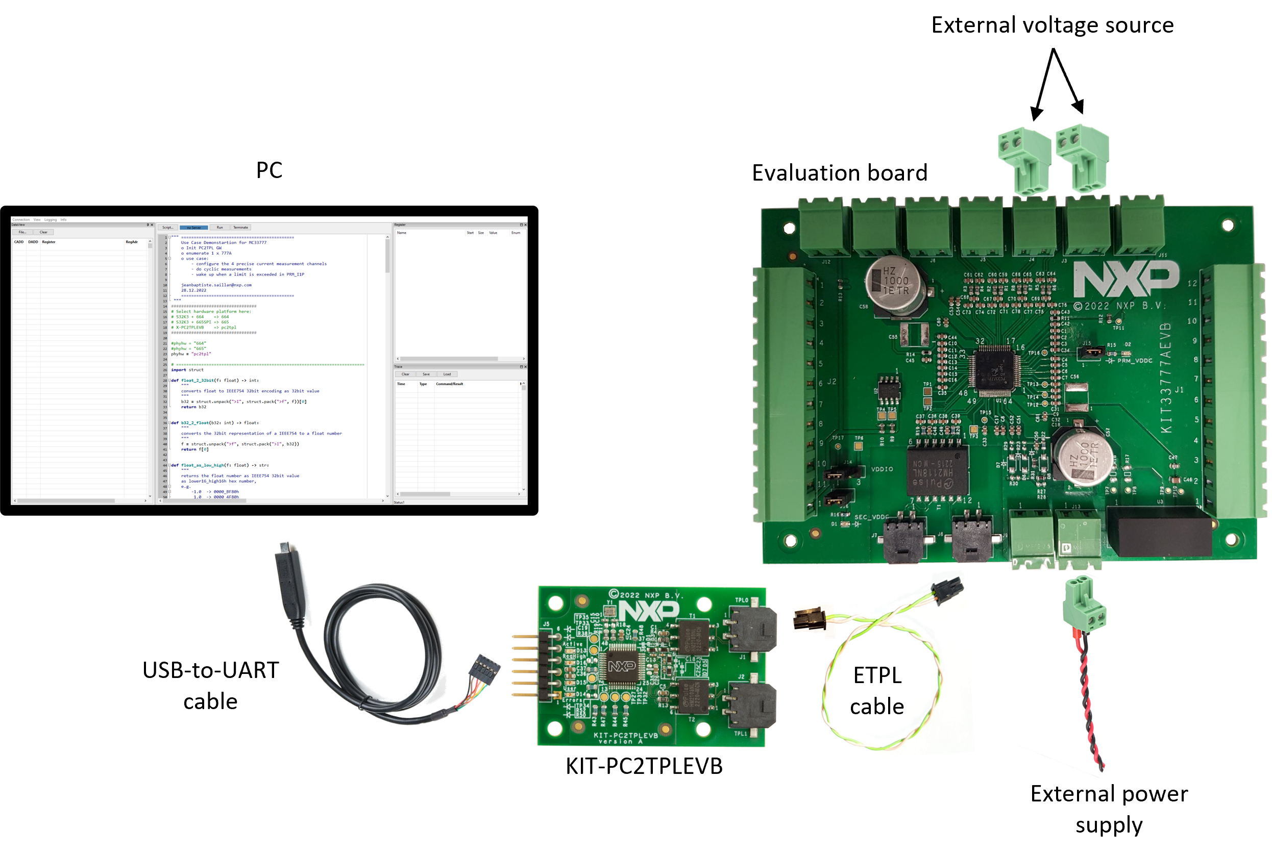
Table 4 lists the material required to set up the test.
| Material | Characteristics |
|---|---|
| Personal computer | With Windows 7 or higher |
| KIT-PC2TPL communication board | |
| USB-to-UART cable | Included in the KIT-PC2TPL kit |
| EVBMA777T; EVBMA8420T evaluation board | |
| ETPL cable | Included in the EVBMA777T; EVBMA8420T kit |
| Power supply cable | Included in the EVBMA777T; EVBMA8420T kit |
| Interface connectors | Included in the EVBMA777T; EVBMA8420T kit |
| External power supply | Output voltage +24 V, output current +100 mA minimum |
| External voltage source (emulating the current measurement) | Output voltage in [-300 mV; + 300 mV] |
The USB-to-UART cable interfaces the KIT-PC2TPL (connector J5) communication board with the computer (USB port).
The ETPL cable links the KIT-PC2TPLEVB (connector J1) with the EVBMA777T; EVBMA8420T evaluation board (connector J7 or J8).
Design Resources
Additional References
In addition to our EVBMA777T2 page, you may also want to visit: