Getting Started with LS1028ARDB
Contents of this document
-
Get Started
-
Out of the Box
-
Upgrade Software
Sign in to save your progress. Don't have an account? Create one.

Purchase your LS1028A-RDB | LS1028A
1. Get Started
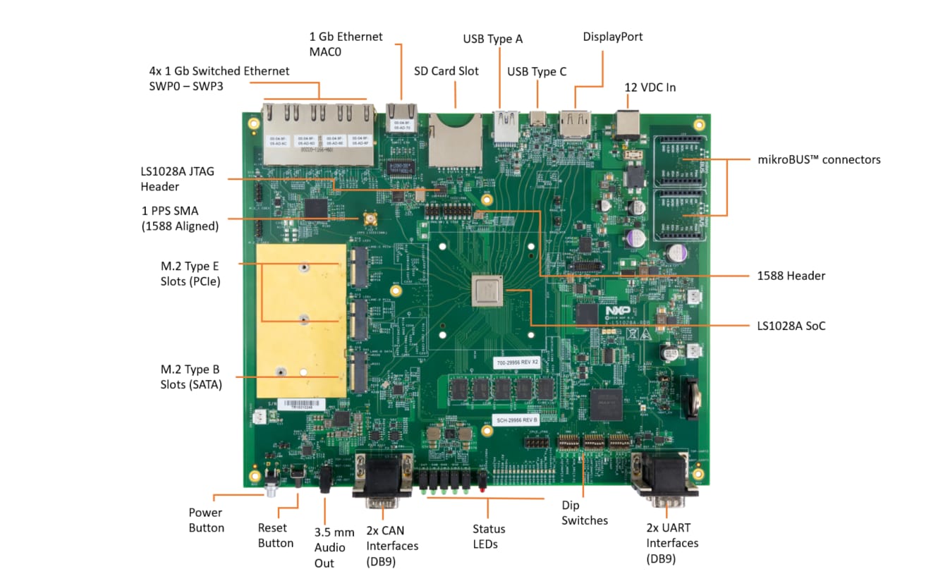
1.1 Get Familiar with the Board
The LS1028ARDB provides a platform for design and evaluation of the LS1028A processor. For details about the features of the board, check our reference manual.
2. Out of the Box
The following instructions will guide you on how to boot the preloaded BSP composite firmware image on the LS1028ARDB board.
LS1028ARDB Kit

The board kit contains the following contents:
- LS1028ARDB hardware assembly with enclosure
- 12 V, 6.67 A AC-DC power adapter
- Universal adapter
- Cable, USB 3.1 Type-C Male to USB 3.0 Type-A Female, 50 mm
- Cable, USB Type-A to DB9F (Windows 10 support), 1 m
- Ethernet cable, 6 ft (min)
- Cable, DB9F-to-DB9F
- Programmed 16 GB SD card
2.1 Connect the board to power supply
Connect the 12 V AC to DC power supply adapter cable to power the jack on the back of the LS1028ARDB chassis and then plug the power adapter into AC power socket. The SYSTEM READY LED on chassis front-side will turn on (Green).
2.2 Set up serial port
Run your favorite terminal application to control and monitor the LS1028ARDB from the serial console. Configure the terminal to 115,200 baud rate, 8 data bits, no parity, and 1 stop bit. To determine the port number of the LS1028ARDB virtual COM port, open the device manager and look under the "Ports" group.
Not sure how to use a terminal application? Try one of these tutorials: Tera Term Tutorial, PuTTY Tutorial.
2.3 Boot the board
Plug the SD card (programmed with the latest BSP composite firmware) in the SD card slot available on the chassis back panel.
Press the power button available on the chassis front panel.
The SYSTEM READY LED on chassis front-side turns on (Green).
The board boots up and the console shows U-Boot messages.
2.4 Congratulations Board has booted to TinyDistro Linux
After U-Boot, if you do not enter any key to avoid autoboot, the board automatically boots to TinyDistro Linux prompt.
If you do not use SD card on the board, the board automatically boots to Linux prompt from the eMMC card available on the board.
Use the following default credentials to log on to to the TinyDistro:
◦ root/root
3. Upgrade Software
3.1 Upgrade board software
LS1028ARDB system is shipped with a 16GB SD card.
Follow the steps below to upgrade the SD card to latest LS1028ARDB software release.
-
Download the latest SD card image from the NXP Website:
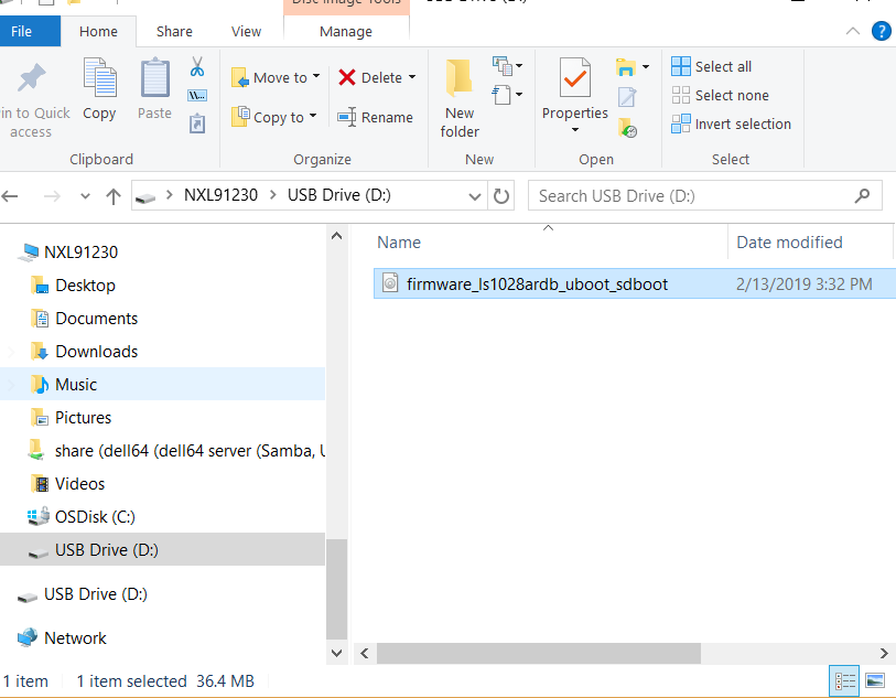
firmware_ls1028ardb_uboot_sdboot - Copy the firmware_ls1028ardb_uboot_sdboot.img to SD card using a Linux machine or Windows machine. The factory SD card only has one FAT partition , copy the image to the FAT partition. Below is an example using a window machine:
- Insert the SD card to LS1028ARDB system
- Power up the LS1028ARDB system and stop the boot process at U-boot as following:
-
Use the following commands to update the SD card
- fatls mmc 0:1
- fatload mmc 0:1 a0000000 firmware_ls1028ardb_uboot_sdboot.img
- mmc write a0000000 8 75000
- setenv bootcmd 'qixis_reset sd'
- saveenv
- reset

The system will boot up with the latest image from SD card with a tiny rootfs.
For Ubuntu rootfs, please follow LS1028A BSP release documentation.
For OpenIL industrial solution , please follow OpenIL release documentation.
PuTTY Tutorial
PuTTY Tutorial
PuTTY is a popular terminal emulation application. This program can be used to display information sent from your NXP development platform's virtual serial port.
- Download PuTTY using the button below. After the download, run the installer and then return to this webpage to continue.
- Launch PuTTY by either double clicking on the *.exe file you downloaded or from the Start menu, depending on the type of download you selected.
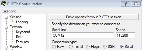
- Configure In the window that launches, select the Serial radio button and enter the COM port number that you determined earlier. Also enter the baud rate, in this case 115200.
- Click Open to open the serial connection. Assuming the board is connected and you entered the correct COM port, the terminal window will open. If the configuration is not correct, PuTTY will alert you.
- You're ready to go
Tera Term Tutorial
Tera Term Tutorial
Tera Term is a very popular open source terminal emulation application. This program can be used to display information sent from your NXP development platform's virtual serial port.
- Download Tera Term from SourceForge. After the download, run the installer and then return to this webpage to continue.
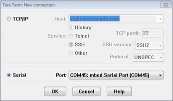
- Launch Tera Term. The first time it launches, it will show you the following dialog. Select the serial option. Assuming your board is plugged in, there should be a COM port automatically populated in the list.
- Configure the serial port settings (using the COM port number identified earlier) to 115200 baud rate, 8 data bits, no parity and 1 stop bit. To do this, go to Setup -> Serial Port and change the settings.
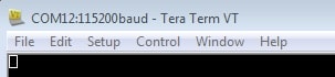
- Verify that the connection is open. If connected, Tera Term will show something like below in it's title bar.
- You're ready to go