Getting Started with the UCANS32K1SIC Evaluation Board
Contents of this document
-
Out of the Box
-
Get Hardware
-
Install Software
-
Configure Hardware
Sign in to save your progress. Don't have an account? Create one.

Purchase your UCAN32K1SIC
1. Out of the Box
NXP analog product development boards provide an easy-to-use platform for evaluating NXP products. The UCANS32K1SIC boards provide a compact form factor for evaluating the S32K1 Automotive MCU, Automotive CAN SIC PHY TJA1463, and applications and protocols such as UAVCAN where you may wish to connect sensors and actuators to a CAN or CAN-FD network. The K1 MCU is powerful enough to also support distributed processing functions within the context of a larger CAN node system, or even function as a standalone device.
This page will guide you through the process of setting up and using the UCANS32K1SIC board.
1.1 Kit Contents and Packing List
The UCANS32K1SIC contents include:
- One UCANS32K1SIC board, assembled and tested
- One CAN cable terminated on both ends (JST-GH 4 pin 200 mm)
- One CAN-TERM-BRD with cable (Rev.B with MicroUSB)
- One DCD-LZ-ADAPT with cable, which provides breakout connectors for SWD / JTAG Debugger and FTDI USB-UART-3 v 3 cable
- One FTDI USB-UART-3 v 3 Uart to USB adapter cable
- Quick Start Guide
The KIT-UCANS32K1SIC contents include:
- Two UCANS32K1SIC boards, assembled and tested
- Two CAN cables terminated on both ends (JST-GH 4 pin 200 mm)
- Two CAN-TERM-BRD with cable (Rev.B with MicroUSB)
- Two DCD-LZ debug adapters with cable, which provides breakout connectors for SWD / JTAG Debugger and FTDI USB-UART-3 v 3 cable
- Two FTDI USB-UART-3 v 3 Uart to USB adapter cables
- One Amotech NFC antenna
- One Segger Jlink mini EDU debugger
- Quick Start Guide
1.2 Additional Hardware
In addition to the kit contents, the following hardware is necessary or beneficial when working with this kit.
- A PC to run the provided graphical user interface (GUI) and program the RD- K344BMU board
- A JTAG debugger, to program the RD-K344BMU board. The recommended debugger is a PE Micro Multilink FX
- An external power supply to use the BATT-14EXTENDER in voltage divider mode (optional)
In addition to the kit contents, the following hardware is necessary or beneficial when working with this board.
- A MicroUSB cable if power is to be applied from a PC through the CAN-TERM-BRD
- A computer/PC
1.3 Windows PC Workstation
This reference design requires a Windows or Linux PC workstation. Meeting these minimum specifications should produce great results when working with this evaluation board.
- Windows 7 or higher operating system or most Linux operating system (Ubuntu 20.04 suggested) with a USB port and any terminal software such as putty
2. Get Hardware
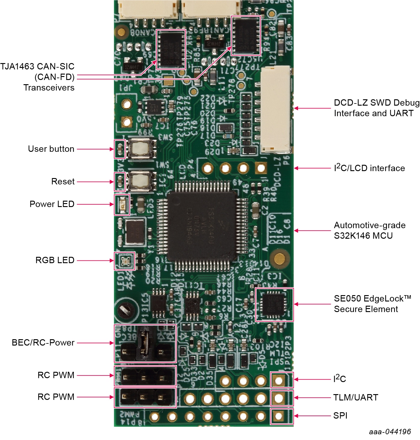
2.1 Board Features
- S32K146 Automotive Processor
- SE050 Secure Element with NFC interface
- TJA1463 CAN SIC (CAN-FD) Transceivers
-
External Interfaces for:
- UART
- SPI
- I²C
- 2x RC-PWM outputs
- Optional RC "BEC" input (external power) for PWM connected devices such as high power servos
- Reset and user buttons
- RGB LED
2.2 Board Description
The UCANS32K1SIC development board is a CAN/CAN-FD node board for connecting sensors, actuators or other peripherals to a CAN-FD bus, and is also suitable for use with drones, rovers and other small (autonomous) vehicles. It is designed to act as a bridge between a CAN bus.
For this purpose UAVCAN protocol software is available for this board using NuttX RTOS and PX4 flight stack.
Any other software including bare metal operation can also be used with this board.
3. Install Software
3.1 Install Software
There are several options for software to run on this board.
- Bare Metal S32K1 SDK example
- NuttX RTOS example with SocketCAN
- PX4/NuttX example with UAVCAN and SocketCAN
- SLCAN CAN over serial for use as a CAN adapter with a PC, and optionally with Wireshark network protocol analyzer
All listed software is available at UCANS32k1
The demo image is based on PX4/NuttX and boots up with data visible on a serial console using the USB-UART cable.
4. Configure Hardware
4.1 Configure the Hardware
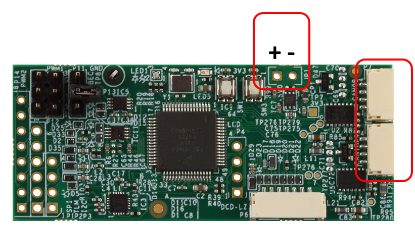
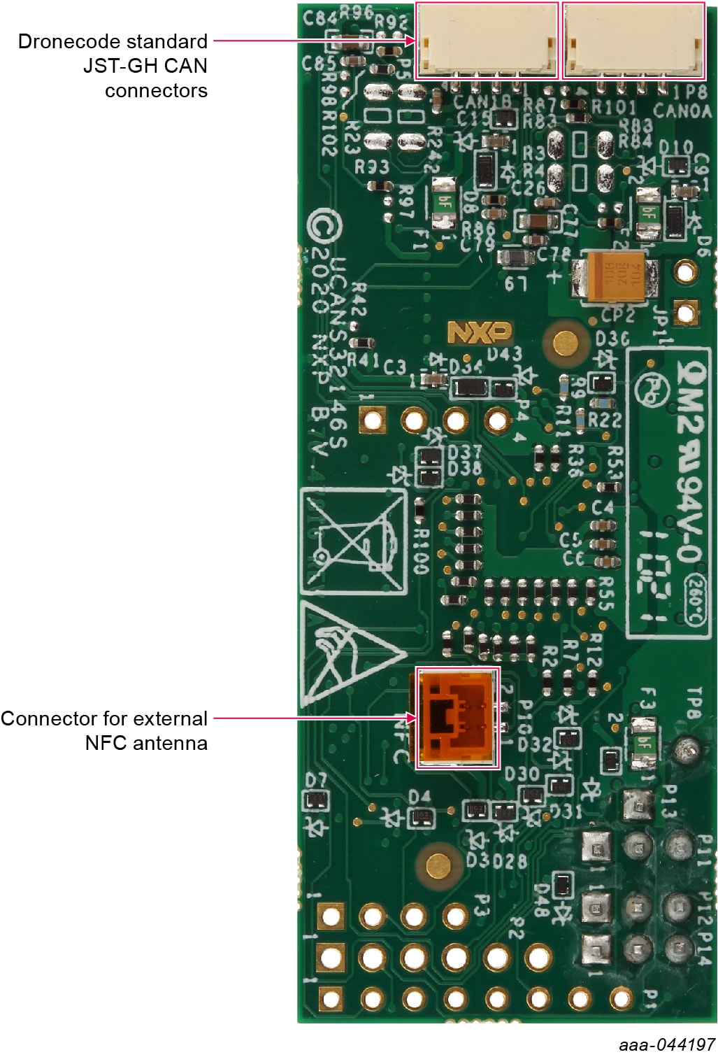
There are two options when powering the UCANS32K146. The first option is to connect 5.0 V power to the power pins on the board. The second option is to power the board through one of the JST-GH CAN connectors. The middle two pins on the CAN connector are for CAN data, and the outer two are for power. The left-most pin is for 5.0 V, and the right-most pin is for GND.
Power can be injected onto the connectors from the CAN bus via the CAN-TERM-BRD. It includes an USB-Mini Connector for application of 5.0 V power.
For demo purposes, plugging a USB-Mini into the CAN-TERM-BRD is the preferred method of powering the board.