Getting Started with the S32RXXXEVB
Contents of this document
-
Plug It In
-
Get Software
-
Build, Run
Sign in to save your progress. Don't have an account? Create one.

Purchase your S32R Evaluation System
1. Plug It In
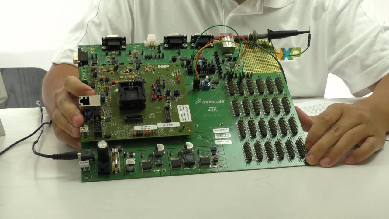
The S32R274RRUEVB is the main evaluation platform for NXP's S32R274 radar MCU. This evaluation board is meant to be paired with the MPC57xxMB motherboard and a radar transceiver such as the TEF810. This page will introduce you to the S32R274RRUEVB's out-of-box experience and showcase some radar applications. Let's get started with your S32R274RRUEVB. You have the choice of watching a short setup video or following the detailed actions listed below.
1.1 Power the Board
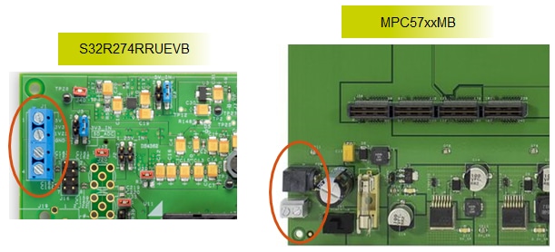
The S32R274RRUEVB supports two power options: through the EVB power terminals or through the MPC57xxMB. The EVB
power terminal requires that the proper voltages be applied to the 5 V, 3.3 V, and
1.25 V ports. This can be most easily generated with a DC voltage generator. The second option, with the motherboard,
requires only a 12 V power supply with a barrel connector. The MPC57xxMB's
various voltage regulators will generate the 5 V, 3.3 V, and 1.25 V supplies from this input and powers both the
MPC57xxMB and S32R274RRUEVB. The S32R274RRUEVB ships being configured for the
second option. To power from the S32R274RRUEVB terminals, you must switch the jumpers J2, J3, J4, J5, and J7 to the
1-2 position, so that the onboard voltage regulators derive their power from
the S32R274RRUEVB rather than from the MPC57xxMB.
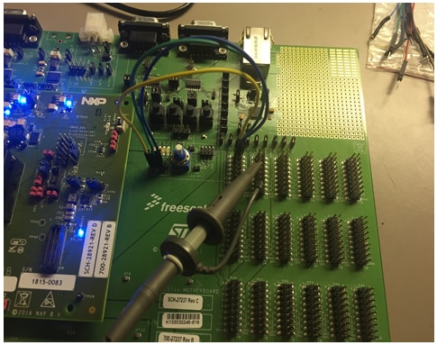
1.2 Build the Out-of-Box Demo Setup
Your S32R274RRUEVB comes with a pre-installed demo. It requires the MPC57xxMB. Connect the CLKOUT pin (P9.7) to an oscilloscope. Also connect the following GPIOs to LEDs: P8.1 to LED P7.1,
P8.2 to LED P7.2, and P8.3 to LED P7.3.
1.3 Run the Out-of-Box Demo
In this demo, the three cores of the S32R274 will take turns controlling the CLKOUT pin. With the clock sources configured to different frequencies, each core drives a different clock source
out of the CLKOUT pin. You will see the oscilloscope waveform change accordingly.
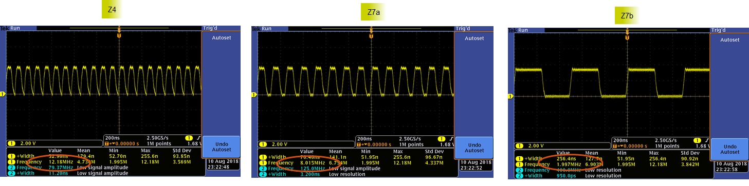
Control of CLKOUT passes from one core to the next every 5 seconds in a round-robin fashion. This switch is timed using the PIT (Periodic Interrupt Timer). Each core will also drive a
different LED. With the described hardware setup, Core Z4 will toggle LED P7.1; Core Z7a will toggle LED P7.2; and Core Z7b will toggle LED P7.3.
2. Get Software
Choose a Development Path:
Learn how to install and run S32R274 sample code.
2.1 Jump Start Your Design by Downloading S32R274 Quick Start Package
Download Quick Start Guide and sample software to kickstart your design.
Get S32R274 Quick Start Package2.2 Install Your Toolchain
NXP offers a complimentary toolchain called S32 Design Studio (S32DS). The S32 Design Studio is an Eclipse-based IDE that offers comprehensive software writing and debugging capabilities. It includes a Processor Expert-based SDK, various other libraries, and supports multiple debuggers including GDB and Lauterbach.
Get S32 Design Studio IDE3. Build, Run
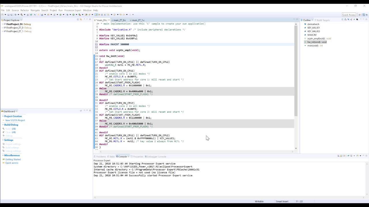
Learn how to create a new project in S32 Design Studio IDE for Power Architecture and the basics to create your own code by running an easy example code.
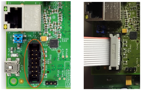
3.1 Connect the Debugger
The S32R274RRUEVB debugs with a JTAG interface. Plug in a JTAG connector to the JTAG port in the orientation shown in the figure. NXP recommends the P&E Micro USB Multilink or
Lauterbach.
3.2 Create, Build and Debug your Application
Software Integration Guide(SWIG) in the Quick Start Package provides easy, step-by-step instructions on how to create, build, and debug projects. Alternatively you can download SWIG from the link below.
For your convenience we integrated example codes in to S32 Design Studio for Power Architecture. Alternatively they can be found in to Quick Start Package. Again Software Integration Guide(SWIG) provides step-by-step instructions on "How to use?".
Not sure how to use a terminal application? Try one of these tutorials:
Tera Term Tutorial, PuTTY TutorialTera Term Tutorial
Tera Term Tutorial
Tera Term is a very popular open source terminal emulation application. This program can be used to display information sent from your NXP development platform's virtual serial port.
- Download Tera Term from SourceForge. After the download, run the installer and then return to this webpage to continue Download
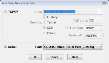
- Launch Tera Term. The first time it launches, it will show you the following dialog. Select the serial option. Assuming your board is plugged in, there should be a COM port automatically populated in the list
- Configure the serial port settings (using the COM port number identified earlier) to 115200 baud rate, 8 data bits, no parity and 1 stop bit. To do this, go to Setup → Serial Port and change the settings
- Verify that the connection is open. If connected, Tera Term will show something like below in it's title bar
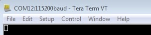
You're ready to go.
PuTTY Tutorial
PuTTY Tutorial
PuTTY is a popular terminal emulation application. This program can be used to display information sent from your NXP development platform's virtual serial port.
- Download PuTTY using the button below. After the download, run the installer and then return to this webpage to continue
- Launch PuTTY by either double clicking on the *.exe file you downloaded or from the Start menu, depending on the type of download you selected
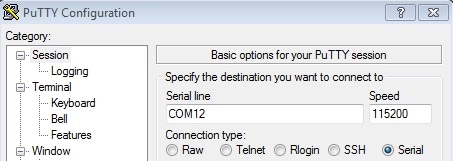
- Configure In the window that launches, select the Serial radio button and enter the COM port number that you determined earlier. Also enter the baud rate, in this case 115200
- Click Open to open the serial connection. Assuming the board is connected and you entered the correct COM port, the terminal window will open. If the configuration is not correct, PuTTY will alert you
You're ready to go.