Getting Started with the S12ZVML-MINIXXX
Contents of this document
-
Plug It In
-
Get Software
-
Build, Run
-
Debug
Sign in to save your progress. Don't have an account? Create one.

Purchase your S12ZVML 3-phase BLDC/PMSM Evaluation Kit
1. Plug It In
Choose between watching a short setup video or following the step-by-step guide.

1.1 Connect the S12ZVML-MINIBRD with the 3-Phase PM Motor
Join motor phase lines into JP1, JP2 and JP3 pins. Hall Sensor lines are not used.

2. Get Software
2.1 Download the S12ZVML-MINIBRD Quick Start Package (QSP)
The Quick Start Package includes the S12ZVML-MINIBRD Quick Start Guide, the S12ZVML-MINIBRD User Guide, S12ZVML-MINIBRD Schematics, and Motor Control Application Software to kick start your design.
Download the S12ZVML-MINIKIT QSP
2.2 Get Your Integrated Development Environment (IDE)
S12ZVML-MINIKIT performs better using CodeWarrior® for MCUs (Eclipse IDE).
Download CodeWarrior® EVAL version
2.3 Get the OSBDM Debug Interface Driver From P&E
Install the latest version of OSBDM hardware driver. Working with the Version 12 (Win XP/Vista/7/8/10).
Go to OSBDM for more information about the OSBDM.
Get OSBDM debug interface drive
2.4 Get the S12ZVML-MINIBRD Motor Control Application Software
Install the complete motor control application software from the Quick Start Package.
The installation process offers downloading the latest version of Automotive Math and Motor Control Library Set.
3. Build, Run
3.1 Choose the Motor Control Driving Control
- BLDC with six-step commutation control
- PMSM with the field-oriented control
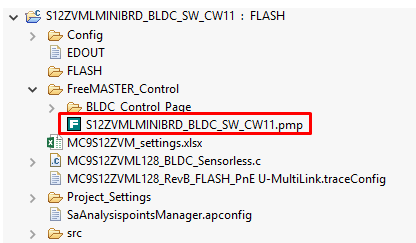
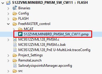
3.2 Import Your Project Into the IDE
In CodeWarrior you should follow: File → Import → General → Existing Project into Workspace And then choose the selected motor control application type.
You can check also an option for copy selected project into your workspace.


3.3 Build the Project - Optional
Right click on the imported project and select Clean project from the context menu. Right click on the imported project and select Build project from the context menu.


On this page
- 1.1
Connect the S12ZVML-MINIBRD with the 3-Phase PM Motor
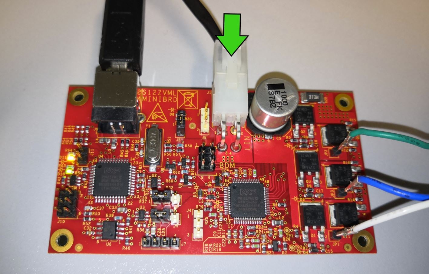
- 1.2
Plug the 12 V Power Supply
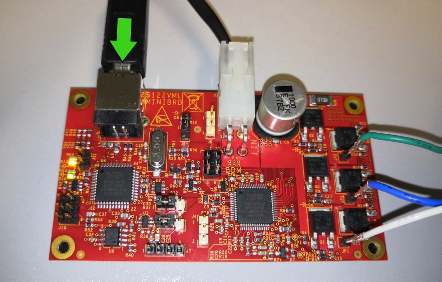
- 1.3
Plug the USB Cable
- 2.1
Download the S12ZVML-MINIBRD Quick Start Package (QSP)
- 2.2
Get Your Integrated Development Environment (IDE)
- 2.3
Get the OSBDM Debug Interface Driver From P&E
- 2.4
Get the S12ZVML-MINIBRD Motor Control Application Software
- 2.5
Get the Run-time Debugging Tool
- 3.1
Choose the Motor Control Driving Control
- 3.2
Import Your Project Into the IDE
- 3.3
Build the Project - Optional
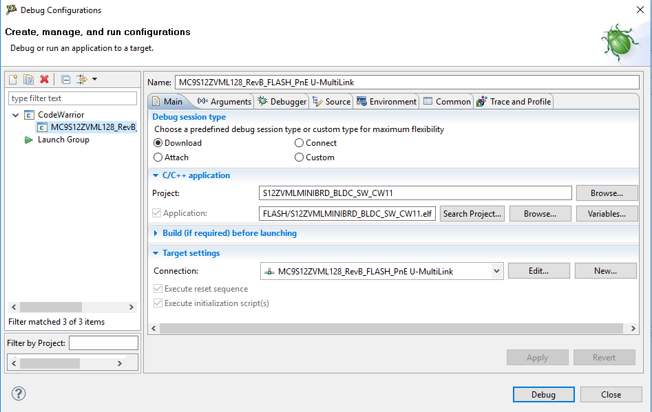
- 3.4
Debug the Loaded Code Into the MCU
- 3.5
Let Code Run and Disconnect