Getting Started with the RDI7014DT1
Contents of this document
-
Plug It In
-
Get Hardware
-
Configure Hardware
Sign in to save your progress. Don't have an account? Create one.
Purchase your RDI7014DT1
1. Plug It In
The NXP analog product development boards provide an easy-to-use platform for evaluating NXP products. The boards support a range of analog, mixed-signal and power solutions. They incorporate monolithic integrated circuits and system-in-package devices that use proven high-volume technology. NXP products offer longer battery life, a smaller form factor, reduced component counts, lower cost and improved performance in powering state-of-the-art systems.
This page will guide you through the process of setting up and using the RDI7014DT1 board.
1.1 Kit Contents and Packing List
The RDI7014DT1 contents include:
- Assembled and tested RDI7014DT1 board in an anti-static bag
- 20 cm 26-pin cell terminal cable
- 20 cm TPL bus cable
- Quick Start Guide
1.2 Additional Hardware
In addition to the kit contents, the following hardware is necessary or beneficial when working with this kit.
- A 7- to 14-cell battery pack or a battery pack emulator, such as BATT-14CEMULATOR
1.3 User Manual
Refer to UM12140, RDI7014DT1 User Manual for additional details on the featured components and board configuration.
2. Get Hardware
2.1 Board Features
- Daisy chain device connection
- LED indicator for operation mode
- Cell-balancing resistors
- Transformer isolation
- Cell sense input with RC filter
- GPIO: digital I/O inputs, wake-up inputs, convert trigger inputs, ratiometric analog inputs, analog inputs with absolute measurements
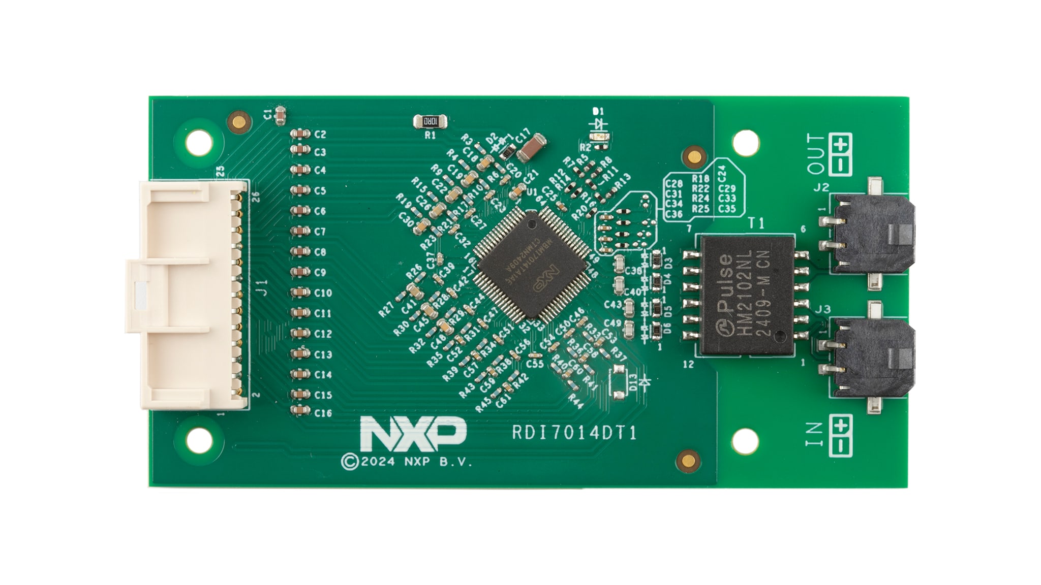
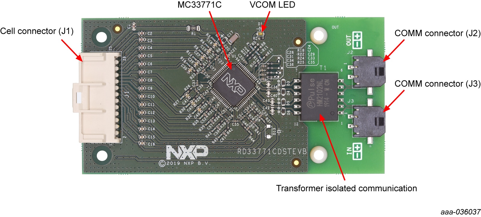
2.2 Board Description
The RDI7014DT1 serves as a hardware evaluation tool in support of NXP's MC33771C device. The RDI7014DT1 is an ideal platform for rapid prototyping of MC33771C-based applications that involve current, voltage and temperature sensing.
The RDI7014DT1 includes a transformer enabling communication in a high- speed isolated communication network. The information is digitally transmitted to a microcontroller for processing.
3. Configure Hardware
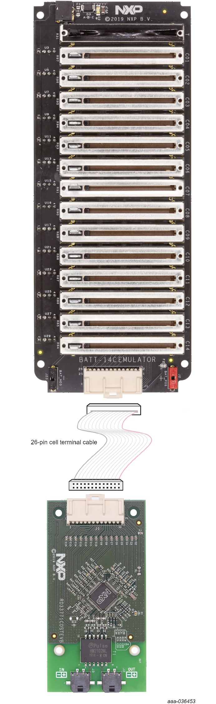
3.1 Battery Emulation Connection
A minimum of 7 cells and a maximum of 14 cells can be monitored. NXP provides a 14 cell battery emulator board, BATT-14CEMULATOR. This board provides an intuitive way to change the voltage across any of the 14 cells of an emulated battery pack and four voltage outputs to emulate four external NTC. The emulator board can be connected to the RDI7014DT1 connector J1 using the provided supply cable.
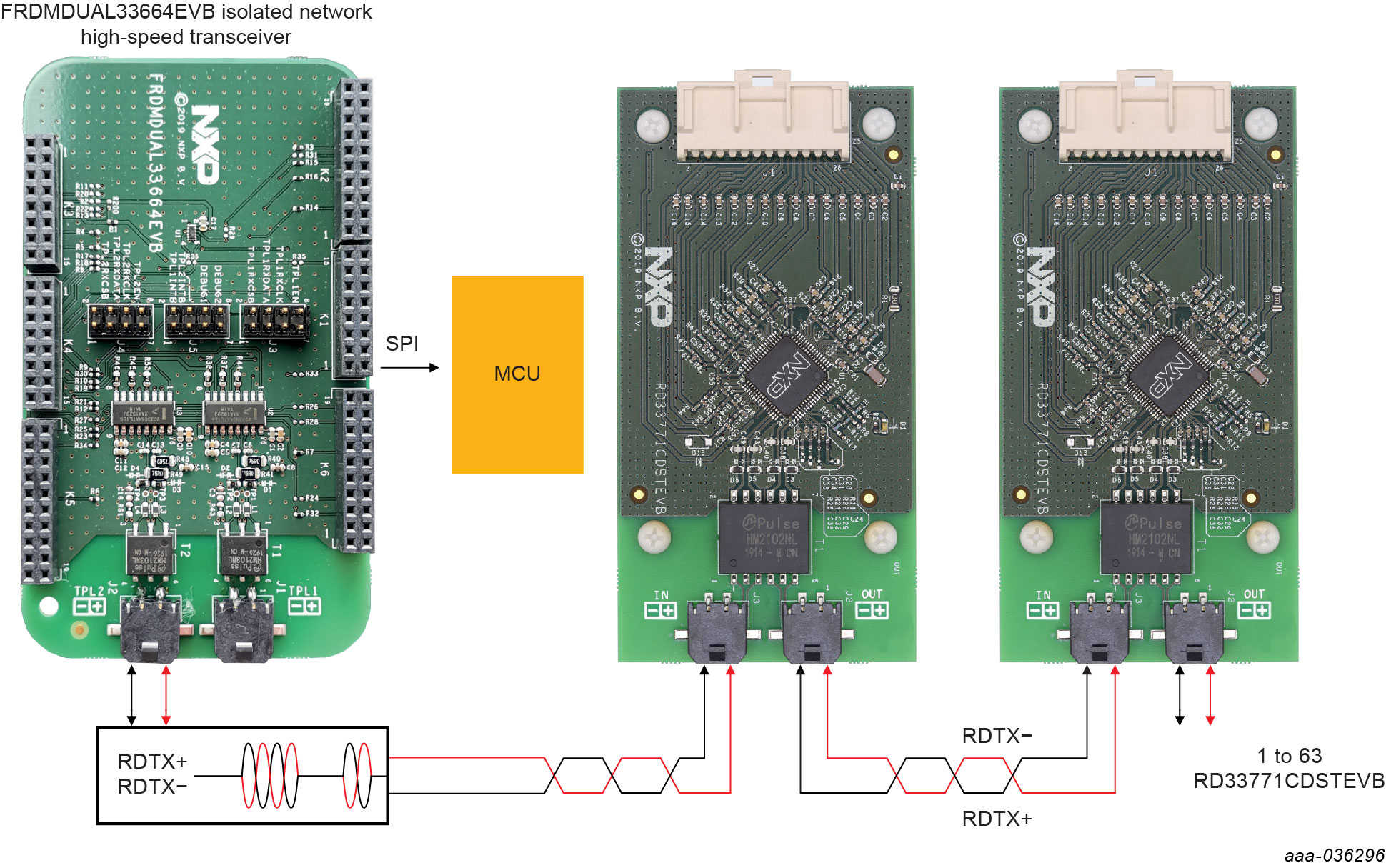
3.2 TPL Communication Connection
In a high-voltage Isolated application with a daisy chain configuration, up to 63 RDI7014DT1 boards may be connected. The TPL connections use the COMM connectors (J2,J3).
3.3 Additional Board Support
Refer to UM12140, RDI7014DT1 evaluation board user manual for additional details on the hardware configuration.