Getting Started with the PTN3944 Evaluation Board
Contents of this document
-
Out of the Box
-
Get Hardware
-
Configure Hardware
Sign in to save your progress. Don't have an account? Create one.

Purchase your PTN3944EVM: PTN3944 Evaluation Board
1. Out of the Box
The NXP analog product development boards provide an easy-to-use platform for evaluating NXP products. The boards support a range of analog, mixed-signal and power solutions. They incorporate monolithic integrated circuits and system-in-package devices that use proven high-volume technology. NXP products offer longer battery life, a smaller form factor, reduced component counts, lower cost and improved performance in powering state-of-the-art systems.
This page will guide you through the process of setting up and using the PTN3944EVMKIT evaluation board.
1.1 Kit Contents/Packing List
The kit contents include:
- Assembled and tested evaluation board in an anti-static bag
- Quick Start Guide
1.2 Minimum System Requirements
This evaluation board requires a Windows PC workstation. Meeting these minimum specifications should produce great results when working with this evaluation board.
- One PC with PCIe x16 Slot, supporting up to PCIe Gen 4 speed
- One PCIe end point device (x1, x2, x4, x8, or x16) supporting up to PCIe Gen4 speed
- One USB-2-DC5V cable to provide power to EVM
- One micro USB cable to connect EVM's USB-2-I²C module to a PC
- EVK boards
- GUI
2. Get Hardware
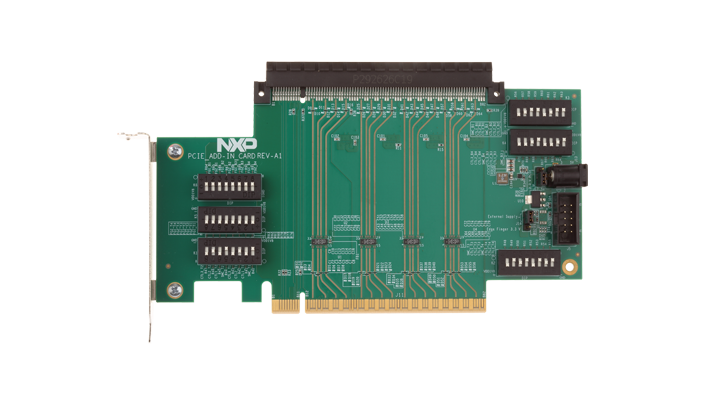
2.1 Board Features
Benefits:
- PCIe x16 gold finger to plug into a PCIe x16 slot
- PCIe x16 CEM connector to connect to a PCIe end point device
- On-board DC-2-DC converter to convert 5.0 V to 1.8 V
- A USB-2-I²C module (LPCUSBSIO) to communicate with GUI to configure PTN3944s
2.2 Board Description
The PTN3944EVM is intended to evaluate PTN3944s for PCIe Gen 4 channel extension using the raiser-card concept. On the PTN3944EVM-KIT, 16 channels of the PCIe buses are routed from the gold finger side to the CEM connector side through 8 PTN3944s, 4 on the front side of the board for TX channels and 4 on the back side of the board for RX channels.
The gold finger side must plug into a PCs PCIe x16 slot for evaluation, but a PCIe endpoint device (x1/x2/x4/x8/x16) can be plugged into the CEM connector side.
An included USB-2-I²C module is used to configure the EVM via a GUI running on a host PC.
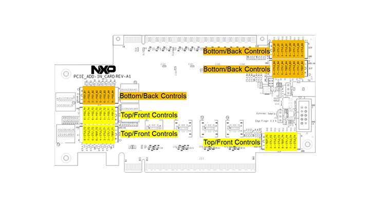
User can configure the equalizer gain settings through either onboard DIP switches, or through the GUI.
3. Configure Hardware
3.1 Set up the Board
By default, board power should be provided through the DC jack (J13) on the board. Make sure that
J16.1-2 and J17.1-2 are shorted with jumpers (by default, these jumpers are installed when
shipped). A USB-2-DC5V power cable is provided to plug into J13. The USB side of this cable should be
connected to a phone charger (5.0 V, 1.0 A) or a PCs USB port to source 5.0 V power.
User can choose to use either hardware or software GUI to configure each TX/RX channel's PTN3944's equalizer gain settings.
To use the hardware configuration:
- When EVMs are shipped, all DIP switches are preset to certain configurations. To change the setting, refer to UM11596
To use the software GUI configuration:
- Users should first download PTN944 GUI from the NXP website. Users are encouraged to first flash the LPCUSBSIO module with the latest firmware, which is located under the GUI package firmware directory. Refer to UM11596 for additional details
- Connect USB-2-I²C module to a PC (via a micro USB cable) and EVM's
J5(via an included 10-pin ribbon cable) - In the GUI package, there is a directory "PTN3944 PCIe" to be used with PTN3944EVM-KIT. When GUI is executed, several default script files that are already pre-loaded in this directory for quick configuration. User can also go through each PTN3944's registers and change the channel equalizer settings manually
Design Resources
Board Documents
Refer to UM11596 , PTN3944 linear equalizer application board for additional details on the featured components and board configuration
- PTN3944EVM Gerber Files
- PTN3944EVM Design Files