Getting Started with the PCA9420UK/PCA9420BS
Contents of this document
-
Get Software
-
Build
-
Create
Sign in to save your progress. Don't have an account? Create one.
Purchase your PCA9420UK-EVM
Get Software
1.1 PCA9420 GUI Software Installation
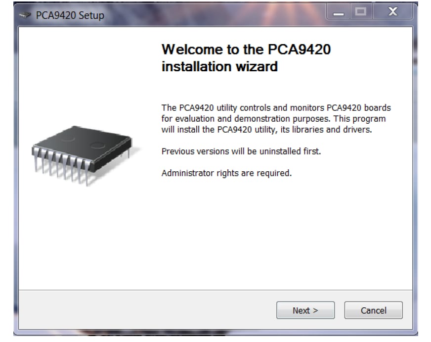
Unzip the provided PCA9420 Evaluation Kit GUI installation execution file, follow the step by step instruction on the screen.
During the installation process, the FTDI interface cable driver will also be installed, please refer to the screen capture for the reference. When correctly installed, the figure shown below on the right pop up on the screen. Click “Finish” button to continue.
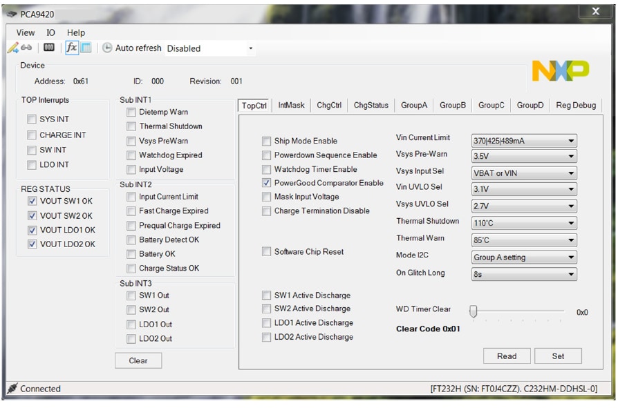
Once the installation finished, the GUI will be automatically launched. Please note that since the standalone evaluation board has not been powered up, no communication channel is established between the computer (GUI) via the interface cable to the evaluation board, and it shows “Disconnected” at the bottom left of the GUI.
Build
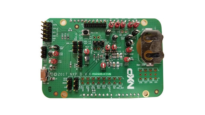
2.1 Board Description
Following figures describe the main elements on the board.
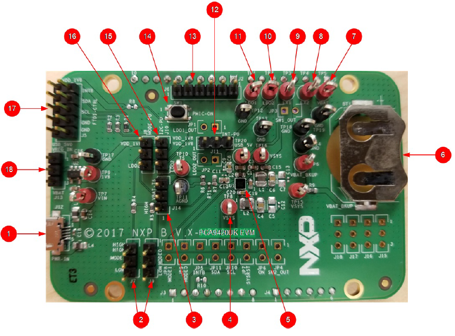
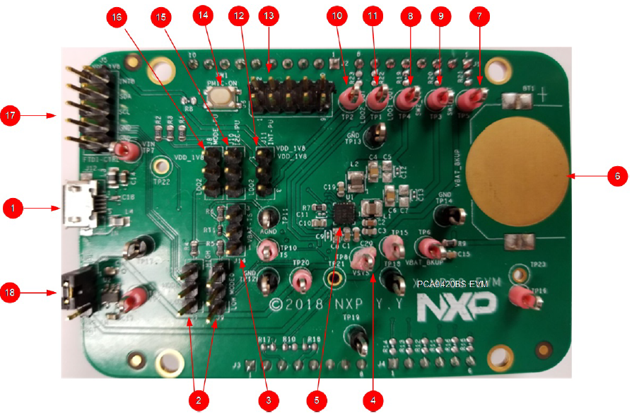
| Number | Name | Description |
|---|---|---|
| 1 | USB Input | USB power supply for the PCA9420UK |
| 2 | Logic pin for MODESEL1 and 2 |
Logic high or low for MODESEL1 and 2 pins |
| 3 | VBAT-TS | TS selection pin for either 10k or 100k |
| 4 | System Node | Electronic load for system |
| 5 | U1 | PCA9420UK PMIC |
| 6 | VBAT_BKUP | Coil cell battery for back-up purpose |
| 7 | VBAT | Connect a Li-ion battery cell |
| 8 | SW2_OUT | BUCK2 output |
| 9 | SW1_OUT | BUCK1 output |
| 10 | LDO2_OUT | LDO2 output |
| 11 | LDO1_OUT | LDO1 output |
| 12 | INT-PU | Interrupt pull-up to either LDO2 output or an external LDO output |
| 13 | PMIC-OUT | All regulators’ output |
| 14 | SW1 | Button connected to ON pin |
| 15 | I²C-PU | Logic voltage selection for I²C |
| 16 | MODE-PU | Logic voltage selection for MODESEL0 and 1 function |
| 17 | FTDI-CTRL | I²C interface |
| 18 | VREG_IN | Input selection for an external LDO between VBAT and USB input |
2.2 Jumper and Switch Definitions
Following figures show the location of jumpers and switch on the evaluation board.
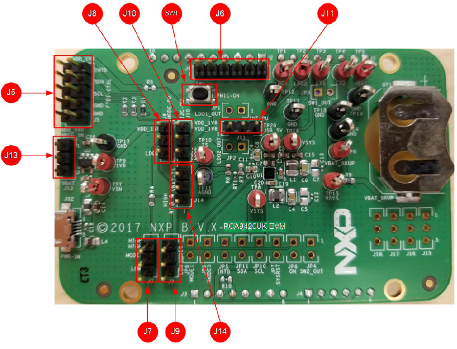
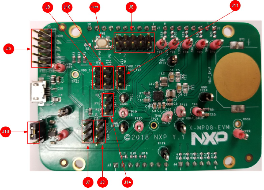
The next table describes the function and settings for each jumper and switch.
| Jumper/ Switch |
Description | Setting | Connection/Result |
|---|---|---|---|
| SW1 | ON | Open | Connect ON pin to ground when pressed. Causes wake-up event of PMIC |
| J5 | FTDI-CTRL | I²C interface connection with FTDI cable. Orange color for SCL, Yellow and Green color for SDA |
|
| J6 | Voltage monitor | Measure voltages for PCA9420UK 1: VBAT 2: BUCK2 output 3: BUCK1 output 4: LDO2 output 5: LDO1 output |
|
| Measure voltages for PCA9420BS 1: BUCK1 output 3: VBAT 5: LDO2 output 7: LDO1 output 9: BUCK2 output |
|||
| J7 | Logic configuration for MODESEL0 |
[1-2] | Logic high |
| [2-3] | Logic low | ||
| J8 | Pullup configuration for MODE function |
[1-2] | Pullup to external LDO output |
| [2-3] | Pullup to LDO2 output | ||
| J9 | Logic configuration for MODESEL1 |
[1-2] | Logic high |
| [2-3] | Logic low | ||
| J10 | Pullup configuration for I/O voltage |
[1-2] | Pullup to external LDO output |
| [2-3] | Pullup to LDO2 output | ||
| J11 | Logic voltage configuration for INTB |
[1-2] | Pullup to external LDO output |
| [2-3] | Pullup to LDO2 output | ||
| J13 | VDD configuration for external LDO |
[1-2] | Pullup to USB input |
| [2-3] | Pullup to VBAT | ||
| J14 | NTC configuration | [1-2] | Pulldown to 100k |
| [2-3] | Pulldown to 10k |
2.3 Connections
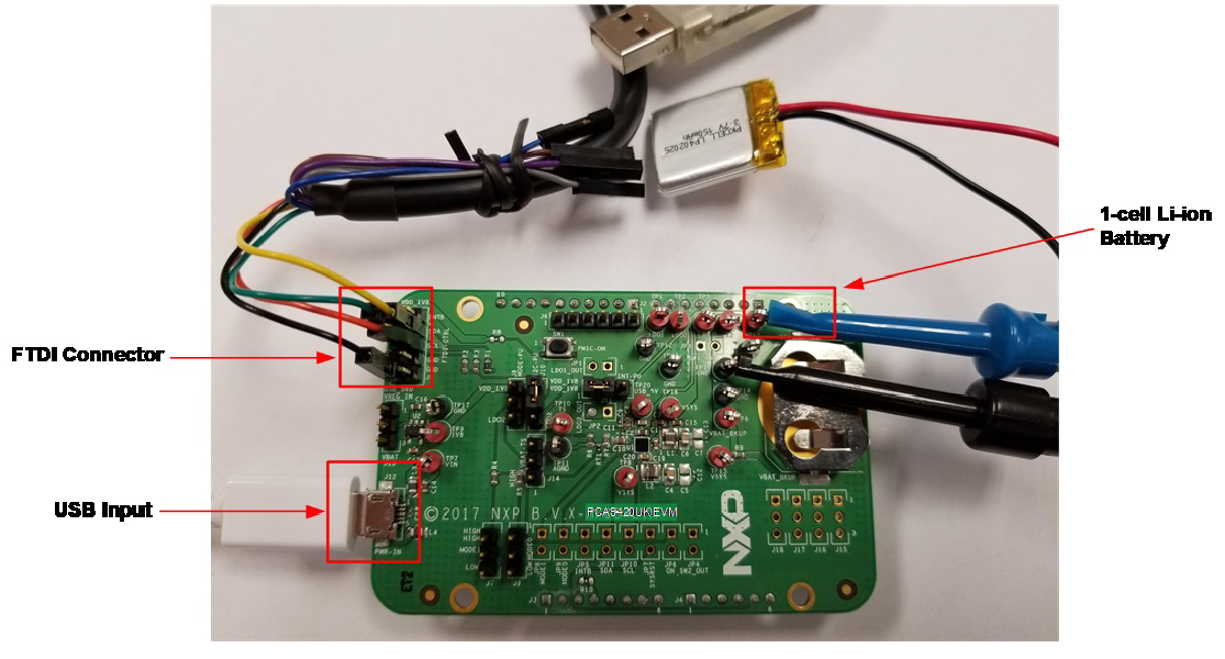
Connect wires on the following pins as shown in the next figure, and make sure the power supply is turned off during the wiring stage:
- A Li-ion battery – Connect to VBAT test point
- VIN Input – Powered by USB Micro B connector
- FTDI Connector – Connect to FTDI USB to I²C cable (Yellow/Green to SDA, Orange to SCL, and Black to GND)
Create
3.1 The GUI Quick Guide
As shown in the next Figure, the GUI is a user-friendly tool which allows access to the on-chip registers to perform write/read commands manually or automatically (depending on GUI setting). Below is a quick guide of the key blocks that the GUI provides.
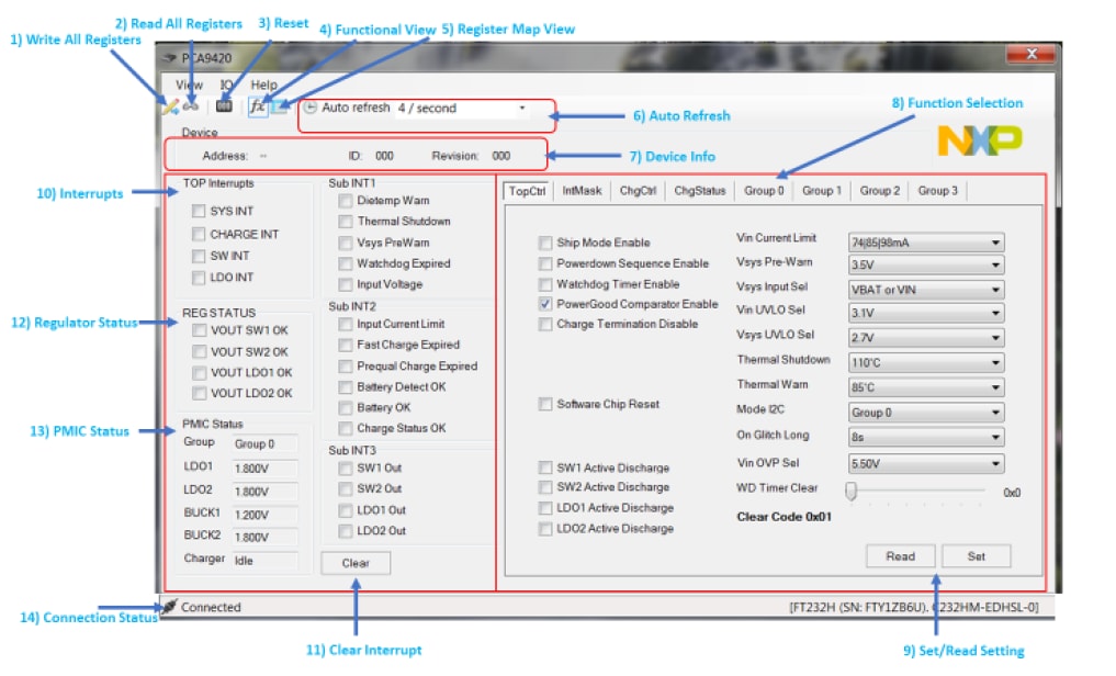
- Write All Registers: Click the write button on the GUI to perform a “write” command to all registers on PCA9420UK/PCA9420BS based on the current GUI setting. It is recommended to disable auto refresh before clicking the write all command, since some of settings might be updated by the auto refresh if turned on
- Read All Registers: Click the read button on the GUI to perform a “read” command and update all the register values reflected on the GUI
- Reset: N.A
- Functional View: By default, the GUI shows the “functional view”
- Register Map View: Click this button to select the Register map view
- Auto Refresh: Sets the auto refresh timer for the Interrupts and Status registers
By choosing different options from the drop-down menu, the GUI performs the backend automatic read and refresh functions accordingly.
- 1/second – Read all registers 1 time per second (1Hz)
- 2/second – Read all registers 2 times per second (2Hz)
- 4/second – Read all registers 4 times per second (4Hz)
- Disabled – Disable the auto read
- Device information: It shows the device ID, device revision and its follower address information. Note that the GUI selects the follower address configured on the evaluation automatically
- Function Selection Tab: All function related registers are grouped into eight different tabs including "Top level control", "Interrupts", "Charging Control", "Charging Status", and "Group A-D setting". Click the tab to access the related registers
- Set/Read Setting: Set/Read the registers on the selected function tab
- Interrupts: Related to register 0x01 (TOP_INT), 0x02 (SUB_INT0), 0x04 (SUB_INT1) and 0x06 (SUB_INT2). When related events happen, the unmasked interrupt bits are set and the GUI highlights the checkboxes and changes the background color to RED
- Clear Interrupt: Related to register 0x02 (SUB_INT0), 0x04 (SUB_INT1) and 0x06 (SUB_INT2). The clear interrupt button is used to CLEAR the interrupt bits. In the case multiple interrupts bits are set at the same time, the button clears all set interrupts bits
- Regulator Status: Indicates the regulator status
- PMIC Status: Indicates current PMIC Status, including selected output group, regulators output voltage setting and the linear charging status
- Connections Status: When valid communication between GUI and the hardware is established, it shows "connected", otherwise it shows "disconnected". The cable used is also shown at the right side of the connection status bar