Getting Started with the NAFE13388-UIM
Contents of this document
-
Out of the Box
-
Get Hardware
-
Configure Hardware
Sign in to save your progress. Don't have an account? Create one.
Purchase your NAFE13388-UIM
1. Out of the Box
The NXP analog product development boards provide an easy-to-use platform for evaluating NXP products. The boards support a range of analog, mixed-signal and power solutions. They incorporate monolithic integrated circuits and system-in-package devices that use proven high-volume technology. NXP products offer longer battery life, a smaller form factor, reduced component counts, lower cost and improved performance in powering state-of-the-art systems.
This page will guide you through the process of setting up and using the NAFE13388-UIM board.
2. Get Hardware
2.1 Board Features
- A complete evaluation platform for the NAFE13388
- Eight input SW configurable AI-AFE
- Easy-to-use GUI-based software demonstrates the capabilities of the NAFE11388 and NAFE13388, which are representative of the AI-AFE family, depending on the part installed on the board
- An external power supply can be used to power the NAFE13388-UIM expansion board
- Convenient test points for easy scope measurements and signal access
- USB interface to the host PC
2.2 Board Description
The NAFE13388-UIM expansion board features a highly configurable, industrial-grade, multichannel analog input AFE (AI-AFE) family of parts that meets high-precision measurement requirements. The device is composed of a low-leakage, high-voltage multiplexer, low-offset drift buffers, a low noise and drifts PGA, a precision 24-bit sigma-delta analog-to-digital converter (ADC), and a low-drift voltage reference.
The AI-AFE family integrates:
- Input protection circuit for electromagnetic compatibility (EMC) and misuse wire scenarios
- Diagnostic circuits for input, open and short circuit and impedance detection
An advanced diagnostic circuit is implemented for channel loopback reading, and output voltage or current bias circuits. The two precise reference voltage sources enable end-to-end system self-calibration and advanced anomaly detection for predictive maintenance.
This NAFE13388-UIM expansion board enables quick evaluation of AFE and plug-and-play compatibility with MCU boards having Arduino connector.
A graphical interface allows the user to easily explore the different functions of the driver. The IC communicates to the host via the industry-standard SPI-bus port. The evaluation software runs under the Microsoft Windows 7, 8, and 10 PC platforms.
2.3 Board Components
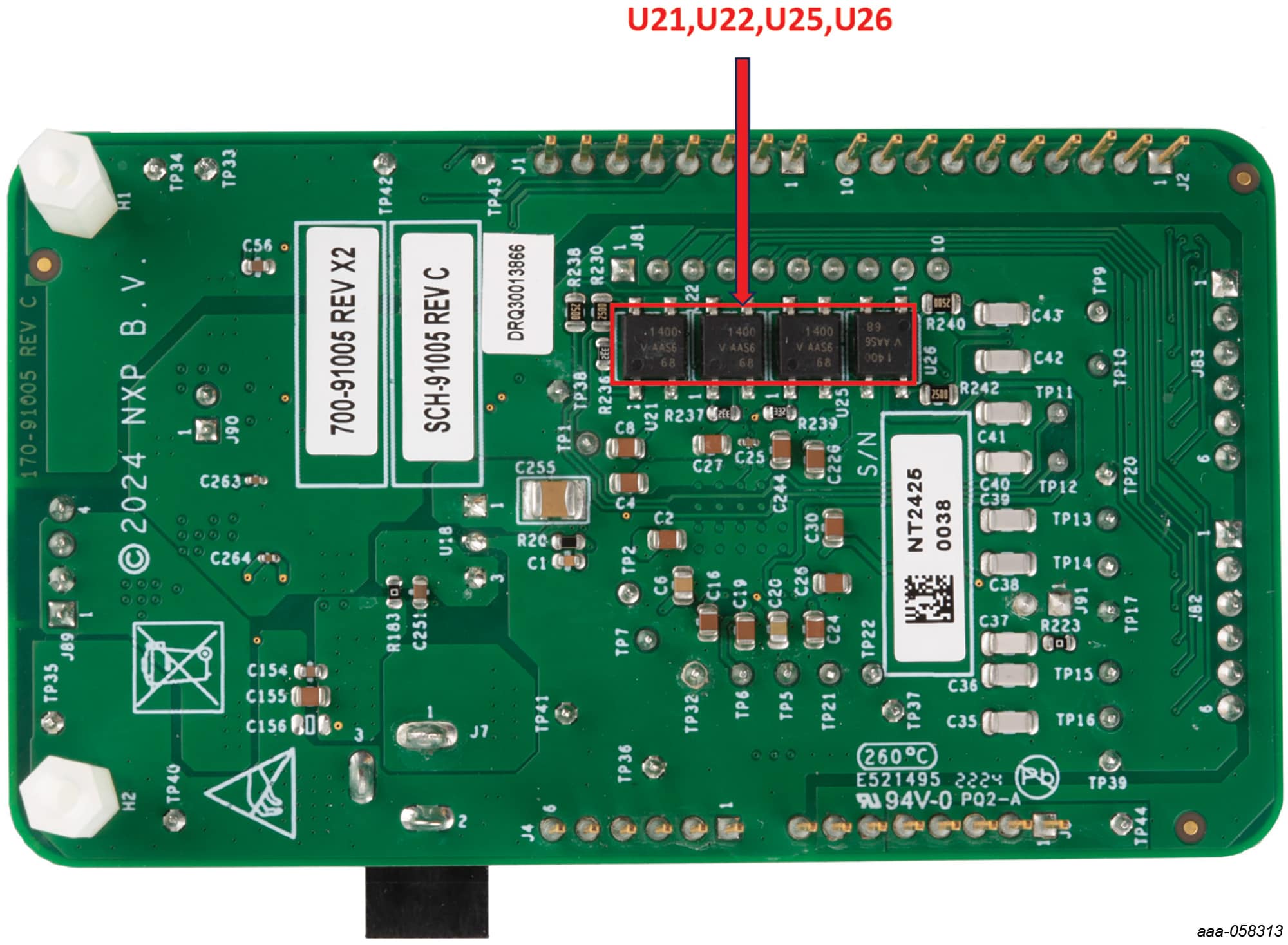
Figure 1 and Figure 2 identify important components on the board and Table 1 provides additional details on these components.
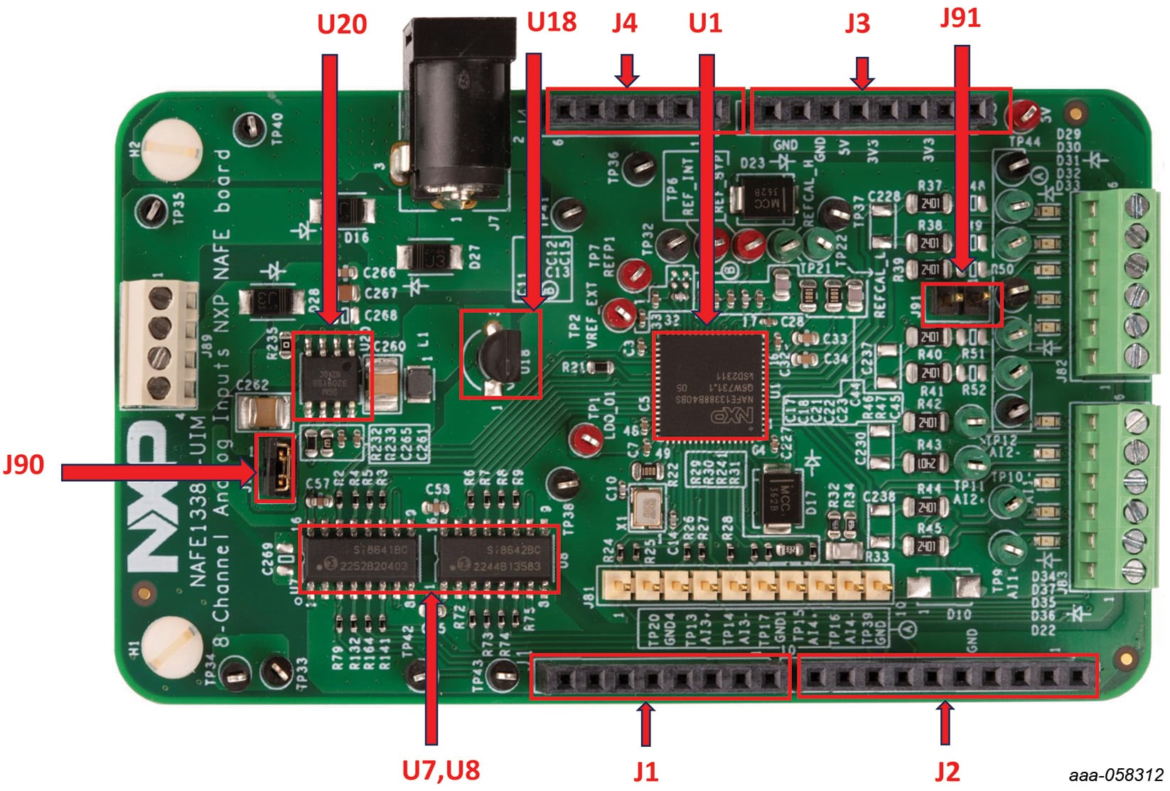
| Device | Description | Location |
|---|---|---|
| Eight-input SW configurable AI-AFE | NAFE13388 | U1 |
| SPST Analog Switches | Switches |
U21U22U25U26
|
| Linear drop-out regulator | LDO | U18 |
| High-Voltage, charge pump DC-DC converter | Charge pump | U20 |
| Quad-channel digital isolators | Digital Isolator | U7U8 |
| Single-line connectors | Mounting connection with FRDM-MCXN board | J1J2J3J4 |
3. Configure Hardware
3.1 Configure Hardware
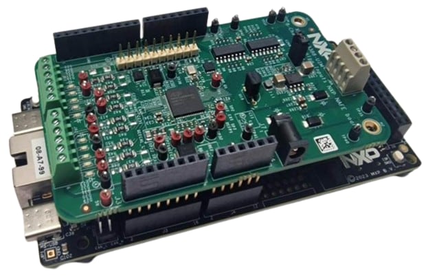
To evaluate a complete solution, a FRDM-MCXN947 evaluation board and a USB cable are needed along with the NAFE13388-UIM expansion board. To set up the hardware, do the following:
- Firmly connect the NAFE13388-UIM expansion board to the FRDM MCXN-947 evaluation board using the Arduino connectors
-
To connect both boards, slide
J1,J2,J3andJ4male connectors at the bottom side of the NAFE13388- UIM expansion board into the appropriate female connectors on the FRDM MCX-N 947 evaluation board as shown in Figure 3 -
Connect a DC power adapter to a DC power jack (
J7) on the NAFE13388-UIM expansion board. Approximately 0.4 V accounts for the voltage drop across the Schottky diode for reverse polarity protection - Use a USB to Type-C cable to connect the PC (USB) to the FRDM-MCXN947 evaluation board
Design Resources
Additional References
In addition to our NAFE13388-UIM page, you may also want to visit: