Getting Started with SLN-LOCAL-IOT
Contents of this document
-
Plug It In
-
Get Software
-
Build, Run
-
Learn More
Sign in to save your progress. Don't have an account? Create one.

Purchase your NXP EdgeReady MCU-Based Solution for Local Voice Control
1. Plug It In
1.1 Unboxing
The SLN-LOCAL-IOT kit arrives in a box as shown below. Inside the box, in addition to the kit, you will find a Quick Start Card.
“Let’s Get Started” and a USB Type-C to dual Type-A cable, as shown in Figure 1. The kit is pre-programmed with an audio playback control demo that is ready to run, as soon as it is powered via the USB cable.

Package and Collateral Content
In addition to the contents listed above, owners of the SLN-LOCAL-IOT development kit can also access a software package containing the SLN-LOCAL-IOT MCUXpresso SDK, precompiled release binaries, and manufacturing tools.
Section 2.2 details how to download these files for yourself using the download code on the Quick Start Card.
1.2 Power On
Plug the USB Type-C connector into the SLN-LOCAL-IOT kit and the dual Type-A connectors into your PC. Figure 2 illustrates how to connect the kit with the USB cable.

When you power on the kit for the first time, you will see the LED cycle through various color patterns, as depicted in Figure 3. These are status indicators for the various stages of the boot process as the chip cycles from internal ROM, to bootstrap, to bootloader, to running the application.
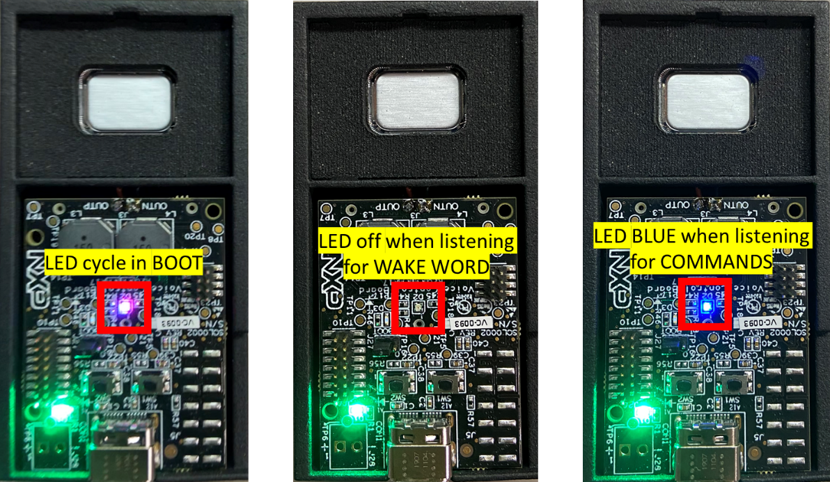
The final step before the device starts listening will turn the LED red for about 2 seconds before turning off. Once the LED is off, the demo is running and listening for the wake word.
To test the demo, say the “Hey, NXP” wake word, followed by a command from the audio playback set (e.g. “Next track”), see section 1.3 for the full list of available commands. The SLN-LOCAL-IOT kit audibly responds to every valid command by playing the phrase, “Intent Detected,” over the built-in speaker. In section 1.4 and section 1.5 we will show how each command is uniquely acknowledged over the serial terminal. Developers can also modify the software to create different physical responses to commands, e.g. toggle a GPIO on the processor to control a switch, playback different audio files over the speaker, or flash different colors on the LED.
1.3 Command Sets
The kit ships with four command sets for control of audio playback (audio), smart home (iot), washing machine (wash), and some generic commands (misc). Only one command set can be active at a time. Audio is the default command set. The active command set can be changed via the serial terminal interface (see section 1.5). The generic commands are intended to be used for proof of concept and prototype developments that need commands that are not available in the other three command sets.
- audio (default – Play, Pause, Start, Stop, Turn On, Turn Off, Previous Track, Next Track, Volume Up, Volume Down)
- iot (Temperature Up, Temperature Down, Windows Up, Windows Down, Turn On, Turn Off, Brighter, Darker)
- wash (Wash Normal, Wash Delicate, Wash Heavy Duty, Wash Whites, Cancel)
- misc (Alpha, Bravo, Charlie, Delta, Echo)
Please contact NXP (local-commands@nxp.com) to discuss the cost and process to create speech recognition models for custom command sets and wake words. The i.MX RT106L solution can support commands sets containing up to thirty commands, in over sixty different languages.
1.4 Connect a Serial Terminal
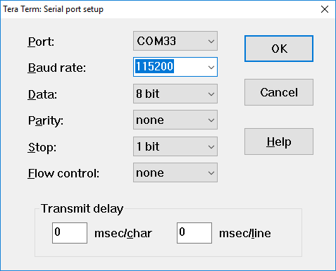
Connect a serial terminal application to the USB serial device interface that enumerates (115200-8-N-1). Figure 4 is a snapshot of serial terminal setup.
Press Enter on the keyboard and you will see the SHELL>> prompt. Type help to
show the available commands. Figure 5 shows the available commands, with a description of each.

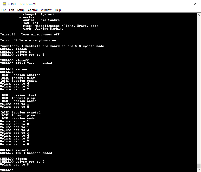
As you use your voice to control the demo, status messages will be displayed in the terminal window showing which command has been recognized. In case of PLAY command, you should see the messages in Figure 6.

1.5 Listing Commands and Changing Command Sets
Type commands to list the active command set and the available commands, as shown in Figure 7.

If you would like to change to a different command set, use the changeto command. For example, switching to the IoT command set would use changeto iot as shown in Figure 8. You can find the other two command sets in Figure 9 and Figure 10.


1.6 Changing the Volume
The shell interface provides a mechanism to change the volume and turn the microphones on / off. In addition, if you would like to change the volume without the shell, SW1 (volume up) and SW2 (volume down) can be used.
Figure 11 shows where these switches are placed on the kit and Figure 12 is a screenshot taken after changing the volume first via the shell, then using the switches.


The default volume of the kit is 50%. Volume is persistent across power cycles.
Use micsoff on the serial terminal to mute the microphone as shown in Figure 13. To unmute, use micson.
When the microphone is muted, the LED turns orange, as illustrated in Figure 14.

2. Get Software
2.1 MCUXpresso IDE
In Section 1. Plug It In, we have shown the unboxing and out-of-box demo experience for those who use the kit first time. This section introduces an integrated development environment (IDE) and the solution’s software development package. Then, in the later sections, we will describe how to build a simple demo project and introduce deeper development guidelines for the local voice control solution.
MCUXpresso IDE brings developers an easy-to-use Eclipse-based development environment for NXP’s microcontrollers based on Arm Cortex-M cores. It offers advanced editing, compiling and debugging features with the addition of MCU-specific debugging views, code trace and profiling, multicore debugging, and integrated configuration tools. Its debug connections support every all NXP’s MCU based development and evaluation kits, including the SLN-LOCAL-IOT kit, with a variety of open-source and commercial debug probes from Arm® and SEGGER®.
To download NXP’s MCUXpresso IDE for free, go to: MCUXpresso
Select MCUXpresso IDE under the PRODUCTS tab.
Go to DOWNLOADS tab and select the LATEST VERSION of the tool. Users will be asked to sign-in/up with a free NXP user-account.
When MCUXpresso installer download completes, double click on the executable, follow the installation instructions and keep the default options.
Launch MCUXpresso IDE, define the Workspace location, and press the OK button, as shown in Figure 15.

2.2 J-Link Debugger
Segger J-Link is a recommended debugger for the SLN-LOCAL-IOT kit. Users need to make sure that the installed J-Link software version is later than V6.60. The J-Link software and documentation pack for various operating systems can be downloaded from J-Link.
2.3 Downloading the Software Package
Follow the steps below to download the software package for the MCU-based Local Voice Control solution.
- Go to Activation
- Log in with a registered user name and password. If an account is not registered on NXP, please register at Register
- After logging in, the user will be sent to the activation page
- Enter into the indicated field the download code from the Quick Start Card that comes with the SLN-LOCAL-IOT kit
- Follow the instructions on the screen
The software package consists of the items shown in Figure 16. This package contains everything that users need to run the demo application and develop custom solutions.

2.4 SLN-LOCAL-IOT SDK
NXP provides the MCUXpresso SDK, a comprehensive software enablement package, designed to simplify and accelerate application developments with NXP’s microcontrollers.
SLN-LOCAL-IOT SDK is a customized MCUXpresso SDK for the Local Voice Control solution. Users can find the SDK, as a .zip file named SLN-LOCAL-IOT.zip, in the SDK folder of the software package. This custom SDK can be used to develop new local voice control solutions with both the i.MX RT106L device and the specific hardware of the SLN-LOCAL-IOT kit. Components of the SDK include an RTOS, middleware (USB, TCP/IP), drivers (MCU and external components), and reference software tools.
Unfortunately, the SLN-LOCAL-IOT SDK is currently NOT available in the MCUXpresso SDK Builder on MCUxpresso. Instead, the custom SDK is only available in the software package downloaded by following the instructions described in section 2.2.
To install the SLN-LOCAL-IOT SDK into MCUXpresso IDE, simply drag-and-drop the SLN-LOCAL-IOT.zip file into the Installed SDKs tab at the bottom of the MCUXpresso IDE. Figure 17 shows a screenshot after installing the SDK.

3. Build, Run
3.1 Importing Projects
In this section we show how to import / build / run example projects in MCUXpresso IDE, where the projects are already available in SLN-LOCAL-IOT SDK. Users will experience how to customize the demo application by simply letting the LED blink when a command is detected.
Prerequisite: a J-Link debugger for 3.3 Programming the SLN-LOCAL-IOT kit and 3.4 Factory Reset in this section. If you do not have such a debugger, then please use the Mass Storage Device (MSD) mode that is described in section 4.2 Firmware Update by MSD mode. You can drag-and-drop your application image into the flash after your application project is built.
The installed SDK allows users to import example applications as a development starting point.
To import an example project, select Import SDK example(s) from the Quickstart pane in the lower left corner of the IDE as shown in Figure 18.

User should see a pop-up window like Figure 19. Select the sln_local_iot option and then proceed by selecting the Next button.

The import wizard, as shown in Figure 20, will then display all the projects that can be imported.

Select demo_apps > local_commands_demo to import the demo application project.
Once the project is successfully imported, it will be listed in the project explorer and ready to build and run.
There are other projects available to import, build, and run. However, we briefly introduce bootstrap and bootloader projects in this section. For more details of all the projects, users are recommended to review developer’s guide that can be downloaded from NXP EdgeReady MCU-Based Solution for Local Voice Control.
The bootstrap project is the first flash-resident application that runs. The bootstrap is a minimal FreeRTOS application that is responsible for verification of the bootloader. The bootstrap firmware is designed to be fixed for the product’s lifetime, since any corruption of this image will result in an unbootable or bricked device.
The bootloader project is the second-stage application that manages signature verification and loading a main application. In addition, the bootloader is responsible for Mass Storage Device (MSD) drag-and-drop and Over-The-Wire (OTW) update of new main application firmware. With the MSD mode, users can simply drag-and-drop new firmware onto the SLN-LOCAL-IOT kit that is connected to the PC via the USB Type-C and dual Type-A cable. With the OTW update mode, users can update a firmware via a wired connection. Currently the SLN-LOCAL-IOT kit supports a UART interface, but it can be extended to support SPI, TCP sockets, I2, and even a wireless connection. There is more information about the bootloader in Section 4. Learn More. For those who are interested in the bootloader, please refer to this section.
For more details of bootstrap and bootloader, please review the developer’s guide that can be downloaded from NXP EdgeReady MCU-Based Solution for Local Voice Control.
3.2 Building Projects
The local_commands_demo is the main application and demonstrates the local voice control capabilities of the SLN-LOCAL-IOT kit.
To build the project, click on the project name in project explorer first. Select the Build option in the Quickstart pane as shown in Figure 21.

The other projects, if imported, can be built in the same way.
As a simple demo experience, we will add a LED blink function in the imported demo project. The LED will blink in three cycles with white, red, and blue colors, when a command is detected.
Open main.c file under sln_local_iot_local_commands_demo > source folder. In the
app_task(), simply add RapidBlinkLED(); within case ASR_COMMAND_DETECTED: {……} as shown in
Figure 22.

3.3 Programming the SLN-LOCAL-IOT
This section describes how to program the compiled demo project into the SLN-LOCAL-IOT kit.
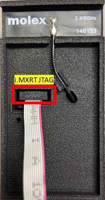
Make sure the 10-pin J-Link connector is connected to the i.MXRT JTAG connector that is located on the backside of SLN-LOCAL-IOT kit, as shown in Figure 23.
Click on the project name that will be programed into the SLN-LOCAL-IOT kit. Click on the Debug button in the Quickstart pane as shown in Figure 24.

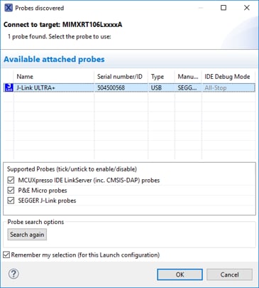
Users should see a pop-up window like Figure 25. Select the J-Link probe that is connected to the kit and press OK.
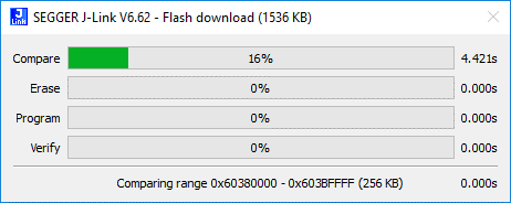
This will launch the flashing tool and proceed to load the image into the flash. The programming status is displayed on another pop-up window like Figure 26. When this is complete, the debugger will be launched and running. Users can then step, run or set breakpoints.
3.4 Factory Reset
It is possible that something can go wrong during development. NXP provides the full 32 MB application binary for the out-of-box demo as part of the software package for the SLN-LOCAL-IOT. Programming this binary onto the SLN-LOCAL-IOT kit will erase the entire flash and replace it with the factory settings.
To restore the kit to the factory state, use the built-in flash programmer in MCUXpresso IDE. The flash tool can be opened by selecting the icon in the image shown in Figure 27.

The Flash GUI Tool will automatically fill in the fields associated with the project that is currently selected.

After the Flash GUI Tool is opened, users might see an error message as shown in Figure 28. The message will disappear if the file to flash is selected.
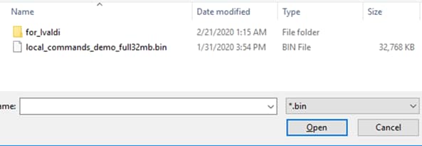
Select the Filesystem button to open a file selection window and select the local_commands_demo_full32mb.bin file from the
Binaries folder of the SLN-LOCAL-IOT software package. Make sure that the file extension type *.bin was selected. Figure 29
shows a screenshot of the binary file selection steps.
In the Base Address field, change the address to 0x60000000 to select the base address of the flash. Clicking on Run… will kick
off the programming operation.
Programming can take up to 10 minutes depending on pc specifications and probe, since the binary is 32 MB in size.
4. Learn More
4.1 Running with Washing Machine Emulator
The downloaded SW package in section 2.3 contains a Graphical User Interface (GUI) emulator for a washing machine. This emulator is intended to present the washing machine control demo. When the SLN-LOCAL-IOT kit detects a command, the emulator shows on screen which command was detected. Please note that the GUI is only available for Microsoft Windows.
Make sure the SLN-LOCAL-IOT kit is plugged in and waiting for the wake word.
Open the Tools/GUI folder in the SW package. The folder structure is shown in Figure 16. Double click the .exe file to execute the emulator. You will see that the command set has changed to wash on the serial terminal, as shown in Figure 30, and a washing machine image like Figure 31 on screen.
Run the washing machine emulator as an administrator on Windows. This allows the GUI to detect the UART port of the kit.

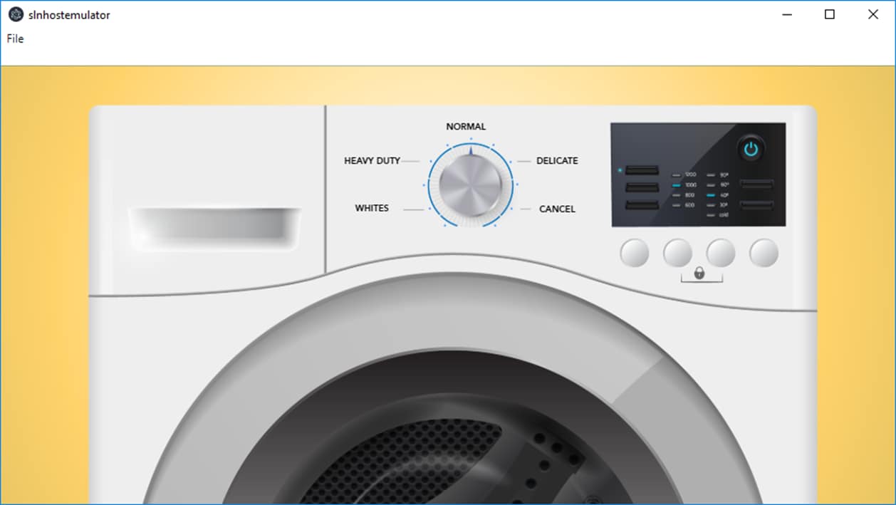
Say “Hey, NXP” followed by one of the wash commands – Wash Normal, Wash Heavy Duty, Wash Delicate, Wash Whites , and Cancel. The emulator indicates which command was detected.
4.2 Firmware Update by USB Mass Storage Device (MSD) Mode
The bootloader application supports firmware update via USB Mass Storage Device (MSD) or Over-The-Wire (OTW) modes. This allows the user to re-flash the main application binary without the J-Link probe. This section describes how to update the main application by USB MSD mode, and the next section introduces the OTW mode.
The firmware update is only for the main application, not for the bootstrap and bootloader. If the bootstrap or bootloader needs to be updated, the user must use j-link probe.
There are two application banks in the flash memory on the SLN-LOCAL-IOT kit.
- Address for Application Bank A:
0x60300000 - Address for Application Bank B:
0x60D00000
The user must configure the bank address properly when the main application is compiled. This ensures that the device is safe to jump into a new application image in one memory location without compromising the other one.
The firmware update is only for the main application, not for the bootstrap and bootloader. If the bootstrap or bootloader needs to be updated, the user must use j-link probe.
If the application currently running is in bank a, the new image must be linked to bank B.
To change the address from Bank A to Bank B, in the MCUXpresso IDE project explorer, right click on the
sln_local_iot_local_commands_demo (or, the user’s application project name) >
Project Settings > Memory, as shown in Figure 32.
Select Edit Memory which will open the Memory Configuration Editor.
Change the address of Flash type to 0x6030 0000 for Application Bank A and
0x60D0 0000 for Application Bank B.

Before building the application, users need to make sure that the MCUXpresso project generates a .bin file as an outcome of the build process. Right click on the project name and open Properties, as shown in Figure 33.
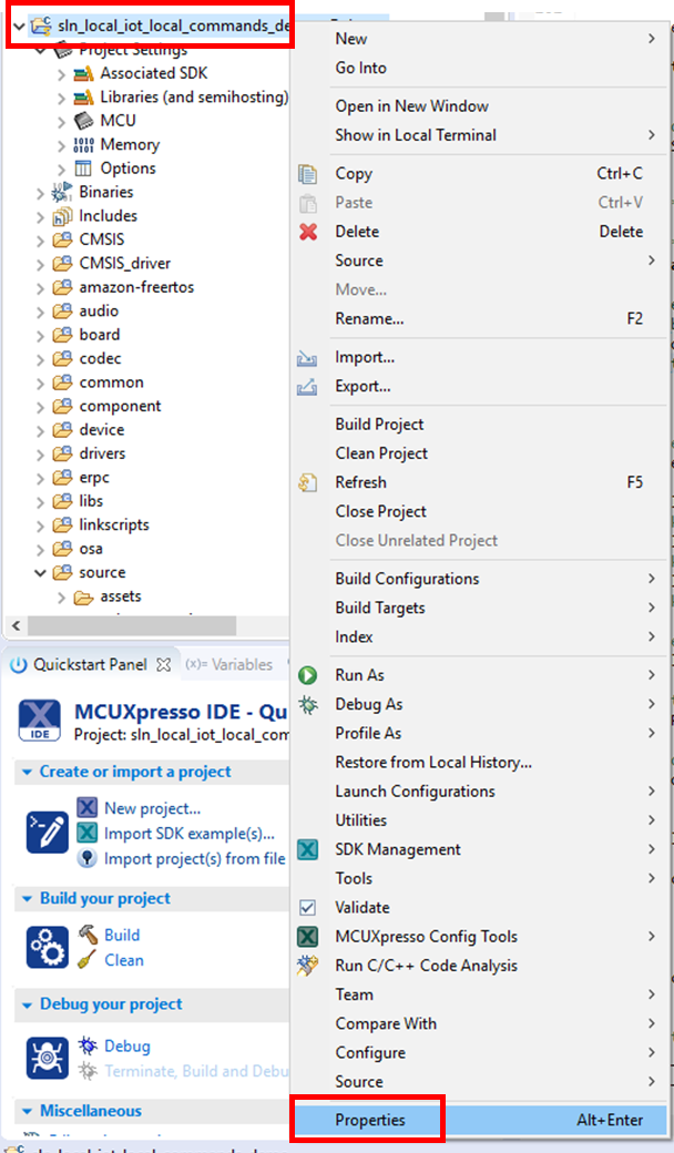
Expand C/C++ Build in the menu and click Settings. Select Build steps tab where Post-build steps can be edited. Click Edit and it will show the commands for the Post-build steps. Figure 34 illustrates how to open the Post-build steps window.

A command character “#” disables all following commands. In order to generate .bin file in post-build process, remove the character “#” and click OK. The resulting commands must look like Figure 35 after removing “#”:

If the build process is done successfully, a .bin file is generated and placed in Debug folder of the MCUXpresso Project.
Now the user can program the generated image into SLN-LOCAL-IOT kit via USB MSD mode.
Power cycle the SLN-LOCAL-IOT kit, while pressing SW2 until the pink LED is illuminated as shown in Figure 36. During MSD mode, the pink LED will turn on and off in 3 second intervals.

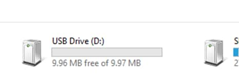
Navigate to the PC’s file explorer and confirm that the SLN-LOCAL-IOT kit is mounted as a USB mass storage drive. A mounted kit is displayed on the file explorer as shown in Figure 37.
Drag and drop the generated .bin file onto the MSD drive. This will start the download process and write the .bin file to flash. After the image has been programmed into flash, it will begin to execute.
4.3 Firmware Update by Over-The-Wire (OTW) Update Mode
OTW update is a process of pushing new application firmware to a device from a remote machine. The device can be connected via UART, SPI, TCP socket, or I2. When the device is updated with the new firmware in the flash memory, it reboots into the new application assuming all necessary checks have passed.
The OTW update for the SLN-LOCAL-IOT kit is driven by using a simple JSON interface, making it easy to implement host side code on the production line. The kit is currently supported by UART but can be extended to support other interfaces such as TCP sockets, SPI, and I2.
There are two types of messages transferred: requests and responses. Each transfer contains two pieces: a 4-byte size field and a JSON message. This allows the OTW data interface to be compatible across a wide range of interfaces. For more details of the request – response flow and the transfer format structure, please review the development guide that can be downloaded from NXP EdgeReady MCU-Based Solution for Local Voice Control.
4.4 Automated Manufacturing Tools
NXP provides a Factory Automation Environment that can be used for securely programming devices on the production line. This collection of scripts is called Ivaldi.
Ivalidi is a package that is responsible for manufacturing programming and reprogramming without needing J-Link. It uses the serial downloader mode of the i.MX RT106L’s boot ROM to communicate with an application called Flashloader that is programmed into the RT106L. Ivaldi was created to focus on the build infrastructure of a customer’s development and manufacturing cycle. Its primary focuses are:
- Factory programming and device set up
- Enabling High Assurance Booting (HAB) and Encrypted eXecute In Place (eXIP)
- Signing images for Application Bank A or Bank B
- Writing and accessing One Time Programmable (OTP) fuses
For more details of the manufacturing tool, please review the development guide that can be downloaded from NXP EdgeReady MCU-Based Solution for Local Voice Control.
4.5 Deep Dive into MCU-based Local Voice Control Solution
More resources including a developer guide, a quick start guide, and the hardware and software design files can be found at NXP EdgeReady MCU-Based Solution for Local Voice Control. Please visit there and explore more about the MCU-based Local Voice Control solution!


