Getting Started with the KITPF7100FRDMEVM
Contents of this document
-
Out of the Box
-
Plug It In
-
Get Software
-
Configure Hardware
Sign in to save your progress. Don't have an account? Create one.

Purchase your KITPF7100FRDMEVM | PF7100 Evaluation Board
1. Out of the Box
The NXP analog product development boards provide an easy-to-use platform for evaluating NXP products. The boards support a range of analog, mixed-signal and power solutions. They incorporate monolithic integrated circuits and system-in-package devices that use proven high-volume technology. NXP products offer longer battery life, a smaller form factor, reduced component counts, lower cost and improved performance in powering state-of-the-art systems.
This page will guide you through the process of setting up and using the KITPF7100FRDMEVM evaluation board.
1.1 Kit Contents
The KITPF7100FRDMEVM contents include:
- Assembled and tested evaluation board and preprogrammed FRDM-KL25Z microcontroller board in an anti-static bag
- USB-STD A to USB-B-mini cable
- Quick Start guide
1.2 Additional Hardware
In addition to the kit contents, the following hardware is necessary or beneficial when working with this kit.
- Power supply with a range of 3.0 V to 5.0 V and a current limit set initially to 1.0 A (maximum current consumption can be up to 7.0 A)
2. Plug It In
2.1 Board Description
The customer evaluation board features the PF7100 power management IC. The kit integrates all hardware needed to fully evaluate the PMIC. The PF7100 on the board is without OTP pre-programmed, allowing the user to define the OTP configuration for the device.
It integrates a communication bridge based on the FRDM-KL25Z FRDM board to interface with the NXPGUI software, to fully configure and control the PF7100 PMIC.
2.2 Board Features
Buck regulators
- SW1, SW2, SW3, SW4, 0.4 V to 1.8 V; 2500 mA; 2 % accuracy and dynamic voltage scaling and single, dual, triple or quad-phase configuration
- SW5; 1.0 V to 4.1 V; 2500 mA; 2 % accuracy
- Configurable VTT termination mode on SW3
- Programmable current limit
- Spread-spectrum and manual tuning of switching frequency
LDO regulators
- 2x LDO regulator 0.8 V to 5.0 V, 400 mA: 3 % accuracy with optional load switch mode
- Selectable hardware/software control on LDO2
RTC supply VSNVSs
- VSNVS1, 1.8 V/3.0 V/3.3 V, 10 mA
- VSNVS2, 0.8 V/0.9 V/1.8 V, 10 mA
System features
- 2.5 V to 5.5 V operating input voltage range
- USB to I²C communication via the FRDM-KL25Z interface
- Selectable hardwire default PMIC configuration or OTP/TBB operation
- Fast mode I²C communication at 400 kHz (high-speed operation supported by PMIC)
- Advance system monitoring/diagnostic via PMIC and/or system AMUX
- Controller/target interface connector
- Onboard I/O regulator with 1.8 V/3.3 V selectable output voltage
2.3 Board Components
Overview of the KITPF7100FRDMEVM evaluation board.
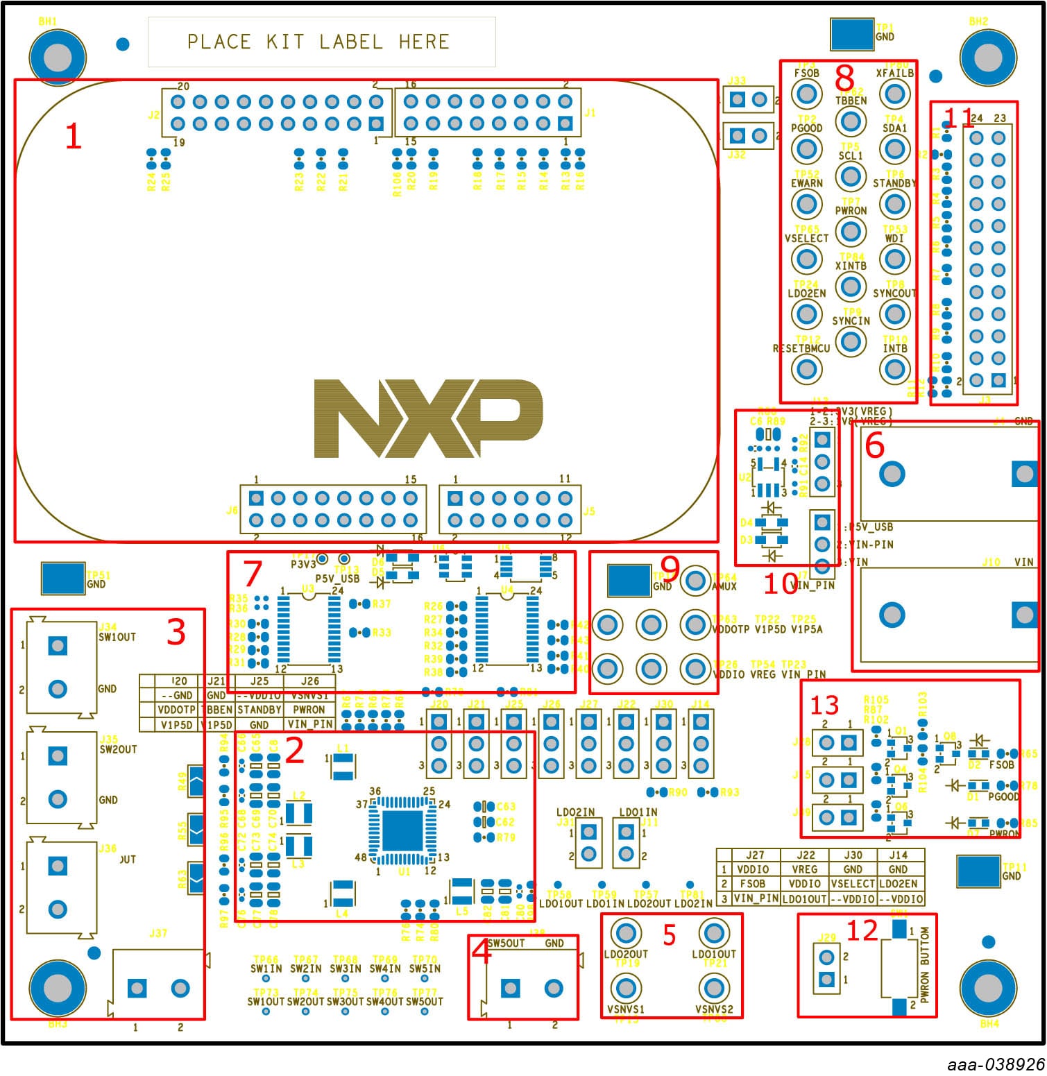
- FRDM-KL25Z FRDM board connector
- PF7100 PMIC
- SW1, SW2, SW3 and SW4 power connector
- SW5 power connector
- LDO and VSNVS power connector
- Input power banana jack
- External analog multiplexer
- PMIC I/O test points
- Analog supplies test points
- 1.8 V/3.3 V external LDO regulator
- Controller/target interface connector
- PWRON button
- IO LED indicator
3. Get Software
The KITPF7100FRDMEVM can use the NXPGUI for any of the PF7100 devices. Prior to the installation of the NXPGUI software and performing device firmware updates (if needed), download and unzip the NXP_GUI_PR_version.zip file to any desired location.
Open and run the NXP_GUI_version_Setup.exe file from the unzipped package. This installs the NXPGUI software in the system. Install it in a local destination folder.
The installation package is available at PF7100 Evaluation Board.
3.1 Updating the PF7100 NXPGUI Firmware
The FRDM-KL25Z FRDM board is used to operate as a communication bridge to interface the NXPGUI with the PMIC and other I²C devices. The firmware is organized in three levels:
- At first level, the SDA uses the BOOTLOADER to operate as the main path to flash the functional code of the SDA processor. The BOOTLOADER is preprogrammed on the FRDM-KL25Z FRDM boards and cannot be reflashed to avoid permanent damage to the FRDM board
- At second level, the SDA provides a firmware loader for quick drag and drop update of the KL25Z MCU firmware
- At the third level, the KL25Z MCU provides the NXPGUI firmware in charge of converting the USB communication into MCU instructions to control digital I/Os, as well as I²C communication to the PMIC
If the FRDM-KL25Z is not loaded with the correct firmware to support a future software upgrade, the firmware can be updated in a few simple steps.
3.2 Flashing the FRDM-KL25Z Firmware Loader
-
Press the push button on the FRDM board and connect the USB cable into the SDA port on the FRDM board. A
new BOOTLOADER device should appear on the left pane of the file explorer. This step is optional and should be
performed only if the FRDM_KL25Z driver does not appear when the SDA port is connected

- Drag and drop the file MSD-DEBUG-FRDM-KL25Z_Pemicro_v118.SDA into the BOOTLOADER drive. File should be located in the KL25Z firmware folder
- Disconnect and reconnect the USB cable into the SDA port (this time without pressing the push button). A new device called FRDM_KL25Z is installed on the PC
3.3 Flashing the NXPGUI Firmware
If a new software or silicon release requires a firmware update on the FRDM-KL25Z FRDM board, use the following steps to upgrade or downgrade the firmware of the FRDM board as needed. Note that this procedure is needed only to update the firmware and may be skipped if no change is needed.
- Connect the USB cable in the SDA port (without holding the push button). The PC installs a new device called FRDM_KL25Z
- Locate the ".bin" NXPGUI driver to be installed, for example nxp-gui-fw-frdmkl25z-usb_hid-pf7100_version.bin and drag and drop the file into the FRDM_KL25Z driver
- FRDM board firmware is successfully loaded
4. Configure Hardware
4.1 Overview
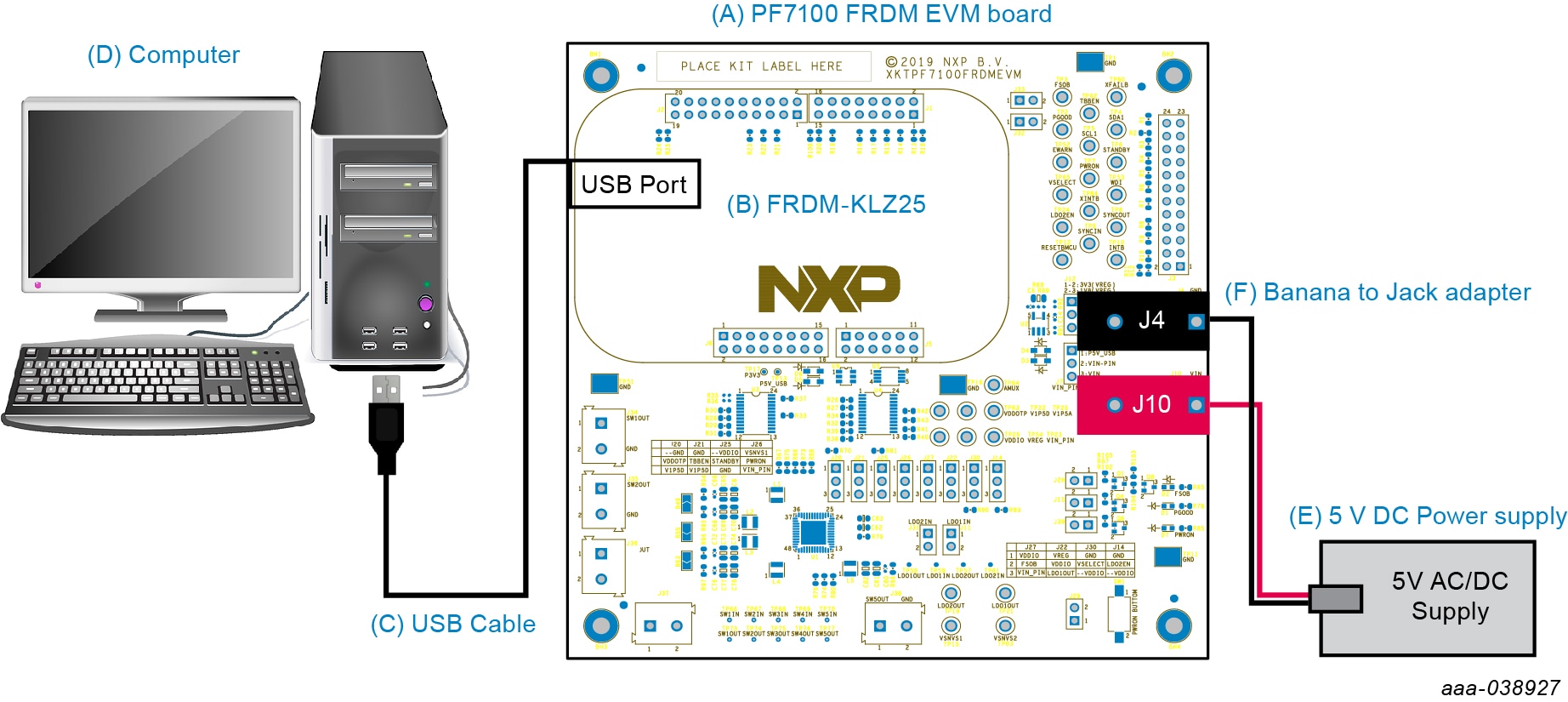
-
Connect the USB cable from the PC to the USB port on the FRDM board and apply VIN to the evaluation board
- Provide external VIN between 3.0 V to 5.5 V on
J10(VIN) andJ4(GND) - Short jumper
J71-2 to provide 5.0 V Vin from FRDM board (use this mode of operation for functional demonstration only, no regulation loading allowed in this mode)
- Provide external VIN between 3.0 V to 5.5 V on
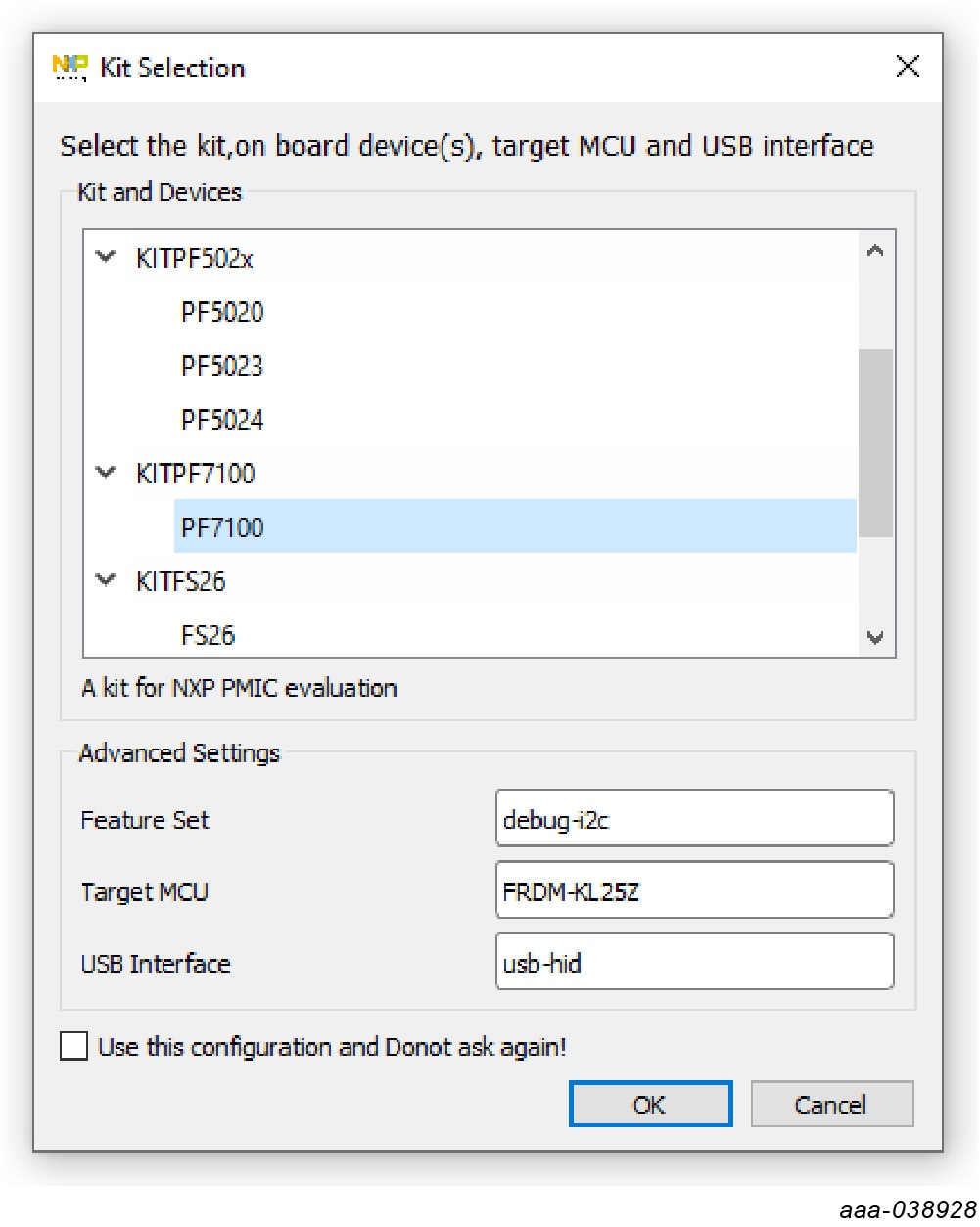
- Open the NXPGUI application from the installation folder or from the Start menu to start the application
- The NXPGUI launcher is displayed with a list of possible configurations to load the NXPGUI. Select the appropriate option for device and silicon revision to be used. If the device revision populated on the KITPF7100FRDMEVM is not available in the list, contact your NXP representative to obtain the latest software update suitable for your device. Click OK to launch the NXPGUI
-
Press Reset on the FRDM board, only if the board is not properly recognized
 The USB-HID connection automatically searches for the KITPF7100FRDMEVM if a valid board is connected. This is
displayed by the active Start button on the top-left corner of the NXPGUI, then click
Start to create a connection.
The USB-HID connection automatically searches for the KITPF7100FRDMEVM if a valid board is connected. This is
displayed by the active Start button on the top-left corner of the NXPGUI, then click
Start to create a connection.
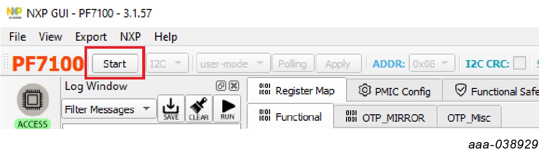 The Start button changes to Stop after clicking. The device status can be read
from the bottom-left corner of the NXPGUI.
The Start button changes to Stop after clicking. The device status can be read
from the bottom-left corner of the NXPGUI.
 Once the device is connected, the system is ready for hardwire or TBB operation as desired.
Design Resources
Board Information
The product summary page for PF7100 is at 7-Channel Power Management Integrated Circuit for High Performance Applications, Fit for ASIL B Safety Level .
Additional Resources
Product Summary Page
The product summary page for PF7100 is at 7-Channel Power Management Integrated Circuit for High Performance Applications, Fit for ASIL B Safety Level .
Tool Summary Page
The tool summary page for the KITPF7100FRDMEVM board is at PF7100 Evaluation Board.
The page provides overview information, technical and functional specifications, ordering information, documentation and software. The 'Get Started' guide provides quick-reference information applicable to using the KITPF7100FRDMEVM board, including the downloadable assets.
In addition to our PF7100: 7-Channel Power Management Integrated Circuit for High Performance Applications, Fit for ASIL B Safety Level page, you may also want to visit:
References
Application pages:
Hardware pages:
Software pages:
Community page: