Getting Started with the FRDM Sensor Toolbox
Contents of this document
-
Plug It In
-
Get Software
-
Run Sensor Demos
-
Evaluate
Sign in to save your progress. Don't have an account? Create one.

Purchase your FRDM Sensor Toolbox Community Edition
1. Plug It In
1.1 Select a Sensor Demonstration Kit
- Go to Sensor Evaluation Boards and select the desired demonstration kit
- Take
FRDM-K64-AGM01demonstration kit as an example
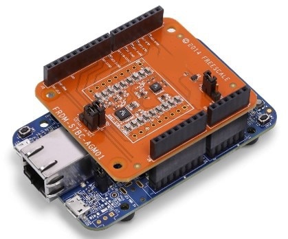
1.2 Plug It In
Connect the "Sensor Demonstration Kit" to the PC via the USB cable between the OpenSDA USB port on the board and the USB connector on the PC.
1.3 Board Settings
All the standard sensor demonstration kits should work out of box with the STB-CE software. These standard kits do not require any jumper changes. In case of custom sensor kits, there are a few jumper modifications recommended.
Find the complete list of all the sensor demo kits with the appropriate jumper settings here.
1.4 OpenSDA
Kinetis FRDM MCU boards are supplied with OpenSDA firmware pre-loaded. For a smooth out of box sensor demonstration with STB-CE, make sure that the latest version of the default OpenSDA bootloader and firmware application is on the FRDM development board. This allows debugging, flash programming and serial communication over a USB cable.
The default OpenSDA firmwares for all FRDM based sensor demonstration kits used with STB-CE are as follows:
- DAPLink:
FRDM-K22F,FRDM-K64F,FRDM-KW41Z,FRDM-KE15Z,RD-KL25-AGMP01 - PEmicro:
FRDM-KL25Z,FRDM-KL27Z
Obtain the latest OpenSDA drivers for FRDM boards from OpenSDA Update to the FRDM boards.
Locate the section "Download – OpenSDA Bootloader and Application" and select your FRDM Board from the dropdown list. Strictly follow the provided instructions to program the board.
For Windows 10 systems, the older versions of the OpenSDA drivers could get corrupted when
the board is plugged on a Windows 10 machine. As a result, many boards might get not
detected as an MSD or a COM port on Windows 10. The latest versions of the OpenSDA software are
compatible with Windows 10 and can be obtained from the link above. The current FRDM-K64F,
FRDM-K22F, FRDM-KL25Z and RD-KL25-AGMP01 boards come with an older version of OpenSDA
drivers from the factory and require a mandatory OpenSDA update.
1.5 PC Configuration
The output data from the provided example applications is provided over the MCU UART. This requires that the driver for the board's virtual COM port is installed on the PC. The board MUST be plugged into the PC before the driver installer is run.
If you have not installed already an ARM IDE toolchain, download and install the Windows drivers corresponding to the default OpenSDA application selected above:
PEmicro Windows Serial Driver mbed Windows Serial Driver
Once the Windows Serial Port Drivers are installed on the PC, determine the port number of the board's virtual COM port by opening the device manager and looking under the "Ports" group.
The demonstration kit is now ready to communicate with the PC.
2. Get Software
2.1 Get Software
Download and install NXP Sensor Toolbox - CE (STB-CE) v2.5 from the download button on the Overview tab. If needed, please see the User Guide for more detailed instructions.

3. Run Sensor Demos
STB-CE enables "Out of Box Sensor Demonstrations and Evaluations" on all the available NXP sensor demonstration kits. The ISSDK firmware and the GUI project are auto loaded providing a plug-and-play experience.
3.1 Launch the Tool and Run Out of Box Sensor Demonstrations
Click on the Sensor Toolbox-CE icon on your desktop. Once the window opens, click on "Out of Box Sensor Demonstrations".

3.2 Follow the Prompts and Launch the GUI
On following the prompts accurately, the appropriate ISSDK firmware will be auto loaded (if required) to the MCU and the corresponding sensor GUI will auto load.
For the chosen example demonstration kit FRDM-K64-AGM01, the AGM01 sensor board
has a 6-axis (Accel, Mag) FXOS8700 sensor and 3-axis FXAS21002 gyroscope sensor. STB-CE
currently provides one out of box demonstrations for each sensor.
Take the FXOS8700 6-Axis (Accel, Mag) demo as an example.
On following appropriate prompts, the ISSDK firmware for FXOS8700 demo will get loaded to the K64F MCU and the appropriate GUI will launch. If the demo kit already has the appropriate firmware, the FXOS8700 6-axis (Accel, Mag) demo will automatically launch without any firmware download.
3.3 Start Demonstration
The GUI project window comprises two different screens - form(s) and the "Register" screens. Therefore, the user will see multiple tabs on launching the GUI, as shown in the images below.
For the FXOS8700 demo example, the forms comprise the accelerometer and the magnetometer GUI as shown below:


Here are some key things that can be observed from the above sensor demonstration with STB-CE:
- Data Streaming: On clicking "Start" on the first tab, the sensor starts streaming acceleration data on the graph at a pre-configured firmware setting of ODR = 100 Hz and Range = ±2 g. The user can also switch to the magnetometer tab and observe the magnetometer streaming data at a pre-configured ODR of 80 Hz
- Sensor Events: Each of the embedded blocks in the accelerometer is enabled with their corresponding settings in the firmware. This enables the user to observe events such as Orientation (Portrait/Landscape), Free-fall, Tap and Vector Magnitude and in real time, along with data streaming
- Data Logging: The user can log both the accelerometer and the magnetometer data to a .csv file to their desired location by simply clicking on the respective "Record" button. This allows the user to perform post-processing/analysis on sensor data
Similarly, all the other available out of box sensor demos provide demo features like Streaming, Logging and Sensor Event detection.
4. Evaluate
Apart from sensor demonstrations at pre-configured firmware settings, each GUI in this tool allows a user to make sensor configuration changes conveniently.
4.1 Sensor Configuration Changes in the Forms
This feature allows a user to make sensor configuration changes in the form(s) in a GUI. This enables a user to make quick changes to critical sensor settings and then stream or log data to see the updated results.
As shown in the image below, in the FXOS8700 demo, the user has the facility to change the power modes, range, ODR and enable/disable events (once in Standby mode) and see the updated results. For example, the streaming data would have an observable noise difference in a "High-Resolution" mode as compared to the "Low Power" mode of the sensor.

4.2 Register Screens: Access the Register Interface of the Sensor
With complete access to the sensor register map with descriptions, this tool provides an easy and intuitive interface for detailed register level evaluation. It enables quick read and writes to single/multiple registers or parameters with ease. It also allows saving user-specific register configurations and loading it later for use. The register operations include:
- Write Data – Used to get the value that needs to be written to the "Register(s)" from the user. The value needs to be in hexadecimal format. If the parameter bits/values are changed, "Write Data" gets updated automatically
- Write – Used to write the value in "Write Data" to the selected "Register(s)" in the sensor
- Read Data – Used to display the selected register's value, read from the sensor, in hexadecimal format
- Read – Used to read the value of the selected register(s) from the sensor
- Read All – Used to read the value of all the "Register(s)" in the active "Sensor Page" from the sensor
- Save Configuration – Used to save the configuration of the selected "Register(s)" in the active "Sensor Page" page to the disk which can be loaded later
- Load Configuration – Used to load back the previously saved sensor configuration. On loading, the sensor configuration gets updated based on the selected configuration file
The image below shows the register screen for the FXOS8700 demo:

4.3 Custom Standalone GUIs
Apart from out of box sensor demonstrations, this tool also supports running standalone STB-CE GUI projects. A standalone project is provided by NXP as a separate package (.stbpkg). To successfully run the custom GUI project, the MCU must have the appropriate firmware loaded.
For more details, please find the User Guide in the Documentation tab.